Contractors most commonly request a load-test report at the wrong project stage — after a supplier has been selected and hardware has been ordered, but before the engineer of record has reviewed the submission. At that point, if the report covers only a bracket or post base rather than the full assembly, or if the tested mounting conditions differ from the actual site substrate, the submission may be rejected and the contractor faces retesting, structural reinforcement, or schedule delay while under peak construction pressure. The gap is rarely a missing document; it is a missing definition of what that document needs to prove. Knowing which questions to raise before approval — about test scope, load type, anchor conditions, and post spacing — determines whether existing evidence is sufficient or whether the project absorbs the cost of filling gaps that were knowable at procurement.
Load testing questions before contractor approval
The first error most procurement sequences make is treating the load-test report as a delivery item rather than a scoping decision. Before requesting documentation, the contractor needs to know what the evidence actually has to cover — because the answer changes depending on the installation context.
Two structurally different methods can be used to demonstrate load compliance: physical testing and engineering calculation. Neither automatically supersedes the other, but each has a different relationship to real site conditions. A physical test produces measured performance data, but only for the configuration that was tested. A calculation can be adapted to project-specific geometry — post spacing, anchor type, substrate — but its accuracy depends on the inputs and assumptions used. Requesting one without specifying which is needed, and under what conditions, often produces a report the engineer of record cannot accept without supplemental information.
The lab-versus-site-test distinction compounds this. A controlled laboratory test may idealize the mounting and anchor conditions in ways that do not match a field installation on masonry, concrete topping slab, or structural steel. That does not make lab test data invalid, but it does mean the contractor needs to understand the conditions under which data was generated before treating it as directly applicable. Where project-specific computations are required — as they often are under specification sections governing railing systems — a generic catalogue test report may not satisfy the engineer’s review without additional documentation tying the test setup to the actual installation geometry.
| Question to Ask | Why It Matters | What to Confirm |
|---|---|---|
| Was load compliance proven by physical test or by calculation? | Calculation may not account for actual mounting; physical test may be idealized. | Whether the evidence method matches site conditions and engineering requirements. |
| Was the test performed in a lab or on the actual project site? | Site tests capture real substrate conditions; lab tests may idealize mounting and anchor conditions. | Which environment the test data represents and whether it reflects site-specific substrate. |
| Does the manufacturer provide structural computations specific to the project’s post spacing and anchor conditions? | Generic reports may not match site layout; project-specific computations are required per Section 05 73 00. | That the provided computations reference the exact installation layout and anchor conditions. |
These questions are most effective when asked before supplier selection, not during submittal review. By the time a submittal package is assembled, the window to request an alternative test setup or project-specific calculation is narrow.
Concentrated load evidence versus general catalogue claims
A catalogue that lists a load figure — say, 200 lb — tells the reader very little without context. The 200 lb concentrated point load and the 50 lb/ft uniform distributed load are not interchangeable; they test different failure modes, and code requirements for top rail performance commonly reference both. A report demonstrating only one leaves the other unverified.
The concentrated point load tests local resistance: the ability of the post, bracket, and anchor to resist a single-person load applied at a fixed point. The uniform distributed load tests continuous pressure across the rail length — the kind of load that represents crowd force or distributed contact. Both represent plausible loading scenarios in occupied spaces, and a failure under one mode does not predict behaviour under the other.
| Load Type | Typical Code Value | What It Tests | Risk if Omitted from Report |
|---|---|---|---|
| Concentrated point load | 200 lb (top rail) | Local resistance and post strength under a single person load | May fail IBC and spec section 05 73 00 requirement for point load, leading to non-compliance. |
| Uniform distributed load | 50 lb/ft (top rail) | Continuous loading over the entire rail length (crowd pressure) | Missing uniform load evidence can leave the rail untested for distributed pressure, causing rejection during review. |
The practical consequence of this gap appears during engineering review, not during procurement. A contractor who accepts a supplier’s load claim without confirming that it addresses both load types may only discover the omission when the reviewer requests the missing uniform load evidence. At that stage, obtaining a supplemental test or calculation adds time and may require hardware re-evaluation if the tested configuration does not match the installed one. Confirming both load types are addressed — before the submittal is assembled — is a straightforward check that eliminates a commonly missed rejection trigger.
For background on how the 200 lb concentrated load figure applies to mounting system design, How to Calculate 200-Pound Load Capacity for Stainless Steel Handrail Mounting Systems walks through the design relationship between load, spacing, and anchor capacity.
Mounting method effects on test interpretation
Load test data describes performance under specific conditions. When the conditions used in the test differ from the conditions on site, the data’s transferability is uncertain — and an engineer of record reviewing the submission is likely to identify that uncertainty before accepting the report.
Three variables most commonly create a mismatch: substrate type, anchor type, and anchor spacing with edge distances. A test performed with anchors set into a controlled concrete pour does not automatically represent performance in a lightweight concrete topping slab, a masonry substrate, or a structural steel embed. Similarly, a test using wedge anchors does not produce directly comparable results to a field installation using epoxy anchors, because the two anchor types have different load-displacement behaviour and failure modes. These are not theoretical concerns; they are the conditions under which engineers ask for retesting or structural reinforcement rather than accepting the submitted data.
| Test-Report Condition | Potential Site Variance | Why It Matters if Different |
|---|---|---|
| Substrate type (concrete vs steel) | Site substrate may differ from lab setup | Test capacity may not transfer; engineers may reject data requiring retesting or reinforcement. |
| Anchor type (wedge vs epoxy) | Field anchor system may use a different type | Anchor capacity and failure mode vary; performance may not be equivalent. |
| Anchor spacing and edge distances | Field layout may have tighter spacing/edge limitations | Code requires reduction factors for spacing/edge distances; capacity may be lower than tested if not specified. |
Anchor spacing and edge distances add a further layer. Even when the substrate and anchor type match, field layout often introduces edge conditions — proximity to a slab edge, a control joint, or an adjacent embed — that require reduction factors applied to the nominal anchor capacity. If the test report does not specify the anchor spacing and edge distances used, the contractor cannot verify whether those reduction factors have already been applied or whether the tested capacity needs to be reduced for the actual layout. That specification gap is not always obvious at first read of a report, but it becomes consequential when an anchor engineer or the engineer of record performs the review.
Rework risks when anchors and brackets are tested separately from the system
Component testing is faster and less expensive than system-level assembly testing. That trade-off is well understood. What is less consistently understood is where component test evidence stops being useful and starts creating approval risk.
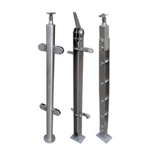
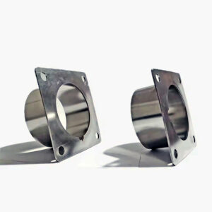
Testing a bracket, a base casting, or a tube section validates that specific component under a defined load condition. It does not verify the load path from the top rail through the connection, down the post, and into the anchor — which is the complete chain an engineer of record must review when approving a railing system under specification sections that assign engineering responsibility for the full assembly. If the component tested is a surface mount base plate and the test load was applied directly to the plate, the report says nothing about how that plate performs when loaded through a post of a specific height, with a handrail applying an offset moment at the top.
| Testing Scope | What It Covers | What It Omits | Risk of Relying Solely on This |
|---|---|---|---|
| Component testing (bracket, post base, tube) | Validates specific hardware strength under defined load | The rest of the load path (top rail, connections, infill, intermediate rails) | Engineer of Record may reject because Section 05 73 00 requires full load path review; component-only evidence insufficient. |
| System-level assembly test | Verifies the complete railing system from top rail to anchor under code loads | Site-specific mounting conditions unless tested in-situ | Lower rejection risk if assembly matches project configuration; still requires verification of mounting substrate. |
The failure pattern here follows a predictable sequence: a contractor receives a component test report from a supplier, submits it as load evidence, and the engineer of record returns it as insufficient because the full load path is unverified. The infill, intermediate rails, and post-to-anchor interaction remain untested. The contractor then needs to request either a system-level test or additional calculations covering the complete assembly — at a point when lead time for supplemental testing is not budgeted. The time cost of that gap is higher than the cost difference between component and system-level testing would have been at the procurement stage.
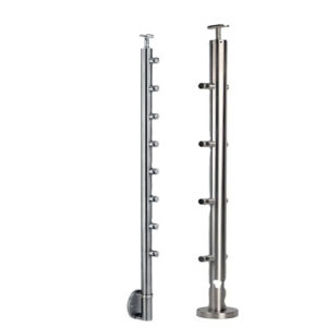
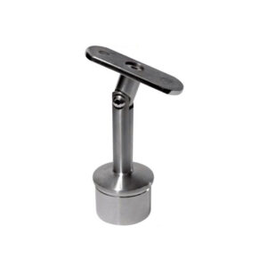
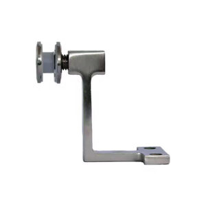
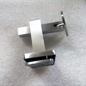
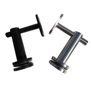
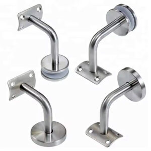
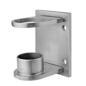
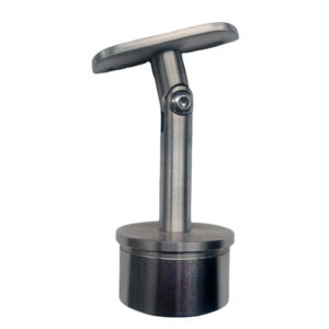
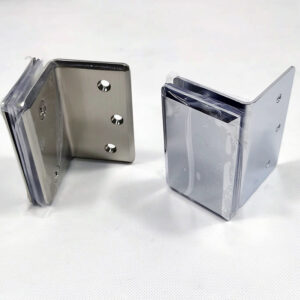
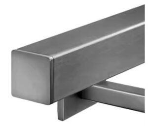
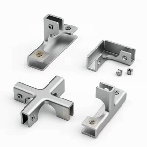
Component test data is useful for hardware comparison and procurement decision-making. It helps identify whether a bracket or base casting meets a minimum strength threshold. But it should be treated as input to a calculation, not as a substitute for one, when the specification requires the engineer of record to verify the entire load path. Heavy duty wall brackets and surface mount base plates are examples of components where hardware-level data supports design review, but the complete system calculation still needs to extend to the rail and anchor interaction.
Approval decision after load path and report scope are confirmed
By the time a contractor is ready to seek approval, two separate checks should be complete: the test report should be in hand, and the design calculations should also be available. The decision friction is that teams often have one without the other, or have both but have not cross-checked them against each other or against the actual project conditions.
Post spacing is the most common discrepancy point. A test report may be built around a specific configuration — post centres at 1.13 m, for example — that does not match the project layout. If the installed design uses wider spacing, the tested capacity is not directly transferable, because bending moment in the rail increases with span. This is not always caught during submittal assembly; it surfaces when a reviewer checks the test report against the structural drawings and finds the geometries do not align. Retesting at a different spacing, or providing supplemental calculations that account for the spacing difference, is the result.
Cross-checking the test data against the design calculations also reveals whether the two documents describe the same physical assembly. If the calculation assumes a specific anchor type and the test was performed with a different one, the two documents are not internally consistent, and the reviewer has grounds to reject the submission. That mismatch is difficult to defend under engineering review, and correcting it requires either updated calculations or a new test — neither of which is fast to obtain once construction has begun.
| Verification Item | Why It Matters | What to Confirm |
|---|---|---|
| Post spacing in test report | If test spacing differs from design layout, capacity may not transfer; mismatch leads to rejection/retesting. | Test report specifies post centres (e.g., 1.13m) matching project spacing. |
| Cross-check test data with design calculations | Discrepancies indicate non-matching conditions (anchor type, assembly, spacing) that would cause review rejection. | Test setup (post spacing, anchor type, assembly configuration) aligns with calculation inputs. |
| Scope of tested assembly | If only a component (bracket/post) was tested, infill and intermediate rail loads are unverified; code requires separate loads for top rail, handrail, infill. | Report identifies that the tested assembly is the complete system or appropriately covers all loaded elements. |
Approval should be conditioned on knowing what was tested. If the report covers only a component, the contractor needs to confirm that supplemental evidence — calculations or a system-level test — covers the elements the component report omits: infill loads, intermediate rail loads, and the complete anchor interaction. If the report covers a full assembly, the contractor still needs to verify that the tested configuration matches the project’s post spacing, substrate, and anchor conditions before treating the data as directly applicable.
For reference on how OSHA load requirements interact with documentation scope, What Are OSHA Load Requirements for Stainless Steel Handrails? covers the 200 lb concentrated load in the context of documentation and testing expectations.
The questions that determine whether a load-test report can support approval are not difficult to ask, but they need to be asked before the report is received rather than after. Defining the anchor type, substrate, post spacing, and required load types — concentrated and uniform — before requesting documentation sets the scope that makes the received evidence usable. Without that definition, contractors frequently receive a report that addresses only part of what the engineer of record needs to see.
The downstream consequence of an underspecified request is not just a rejected submittal. It is retesting or supplemental calculation under schedule pressure, at a project stage when both are expensive and disruptive. The check that prevents it is straightforward: confirm that the test report covers the complete load path, that both load types are addressed, and that the tested configuration — post spacing, anchor type, substrate — matches the actual installation before the submittal package is assembled.
Frequently Asked Questions
Q: What if the engineer of record has already been assigned and a supplier has been selected — is it too late to define what the load report needs to cover?
A: It is not too late, but the options narrow significantly. Once hardware is ordered and a submittal is being assembled, requesting an alternative test setup or project-specific calculation from the supplier takes time that is rarely budgeted at that stage. If the report in hand covers only a component rather than the full assembly, or if the tested conditions differ from the site, the contractor’s remaining options are supplemental calculations from a structural engineer or retesting — both of which carry cost and schedule consequences. The earlier the scope of required evidence is defined, the more options remain available.
Q: Can ASTM E935 or ASTM E985 test evidence from one project be reused on a different project without new documentation?
A: Only if the tested configuration matches the new project’s conditions exactly — same post spacing, same anchor type, same substrate, and same assembly scope. ASTM E935-21 and E985-24 test results describe performance for a specific setup. If post spacing differs, bending moment in the rail changes and the capacity figures are not directly transferable. If the substrate or anchor type differs, the load-displacement behaviour may not apply. Reusing prior test data without verifying that those variables align gives the engineer of record grounds to reject the submission and request configuration-specific evidence.
Q: When does a physical load test produce more reliable evidence than an engineering calculation, and when is the reverse true?
A: A physical test is more reliable when the assembly configuration is fixed, repeatable, and matches the tested setup — it produces measured performance data that does not depend on assumed input values. A calculation is more reliable when site conditions vary across the project, because it can be adapted to specific post spacing, anchor capacity, and substrate without running a new test for each variation. The risk with physical testing is that idealized lab conditions may not transfer to field installations on masonry or topping slabs. The risk with calculation is that its accuracy depends entirely on whether the inputs reflect actual site conditions. For most commercial projects, both are used together: test data validates component capacity, and calculations extend that data to the full load path and specific geometry.
Q: If a supplier provides a system-level assembly test rather than a component test, what should still be verified before accepting it as sufficient?
A: Three things remain worth checking even with a system-level report. First, confirm that the post spacing used during testing matches the project layout — a wider field spacing increases rail bending moment and the tested capacity may not apply. Second, verify that the anchor type and substrate in the test match the site conditions, because wedge and epoxy anchors have different failure modes and a mismatch is grounds for rejection. Third, confirm that the report addresses both the 200 lb concentrated point load and the 50 lb/ft uniform distributed load, since a system-level test may still cover only one load type if that was the scope of the test protocol.
Q: Is it worth requesting project-specific structural computations when a system-level test report is already available, or does the test report make the calculation redundant?
A: Both are typically needed, and the test report does not make the calculation redundant. The test report documents performance for the tested configuration. The calculation is what ties that configuration to the actual project conditions — verifying that the post spacing, anchor layout, edge distances, and substrate are consistent with what the test covered, and applying any required reduction factors for field anchor conditions. Under specification sections that assign engineering responsibility to the full railing assembly, the engineer of record will generally need both documents to confirm the load path is verified from top rail to anchor. Treating them as substitutes for each other is a common source of incomplete submittals.