Designing a stainless steel cable railing system requires more than selecting components. The true challenge lies in navigating a complex matrix of structural specifications, building codes, and installation methodologies to achieve a safe, compliant, and visually striking result. A single oversight in post specification or tensioning can compromise the entire system’s integrity, leading to safety failures and costly remediation.
This focus is critical now as building codes evolve and material performance expectations rise. Professionals must move beyond basic component selection to master the engineering principles that govern post systems, ensuring designs meet both aesthetic goals and stringent safety standards.
Core Design and Material Specifications for Cable Railing Posts
Defining Post Function and Material Grade
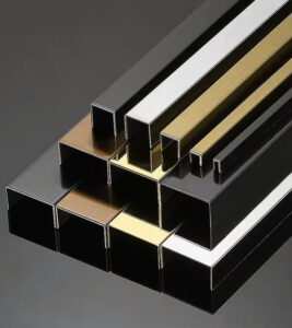
The structural role of a post dictates its required specifications. Terminal posts, which anchor cable runs and house tensioning hardware, must withstand concentrated tensile loads. Intermediate posts primarily guide cables and maintain spacing. This functional bifurcation demands different material strengths. For corrosion resistance, material grade is non-negotiable. Type 316/L marine-grade stainless steel is the standard for coastal or harsh environments, while Type 304/L suffices for general applications. Industry experts note a growing market segmentation, with suppliers promoting advanced grades like 2507 Duplex to target performance-critical commercial projects.
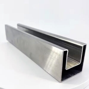
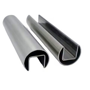
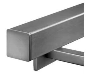
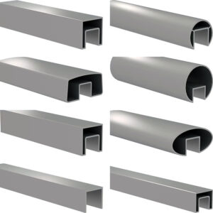
The Critical Role of Wall Thickness and Profile
Wall thickness, measured in gauge, is a direct indicator of a post’s load-bearing capacity. Terminal posts require heavier construction, typically 10-gauge thickness, to resist the pull of tensioned cables. Intermediate posts can utilize lighter 12-gauge material. Posts are commonly fabricated from square or round structural tubing, with the profile impacting both aesthetics and the method of cable integration. According to research from material standards, the quality of the welded tubing, governed by specifications like ASTM A554, is fundamental to ensuring these mechanical properties and long-term performance.
The following table clarifies the core specifications based on post function and environment:
| Post Type | Primary Function | Key Specification (Gauge) |
|---|---|---|
| Terminal/Tension Post | Anchors cable runs | 10-gauge thickness |
| Intermediate/Line Post | Guides cables | 12-gauge thickness |
| Material (Harsh Env.) | Corrosion resistance | Type 316/L marine-grade |
| Material (General Use) | Corrosion resistance | Type 304/L stainless steel |
Source: ASTM A554 Standard Specification for Welded Stainless Steel Mechanical Tubing. This standard governs the material quality and mechanical properties of the welded stainless steel tubing commonly used to fabricate cable railing posts, ensuring structural integrity.
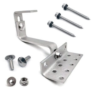
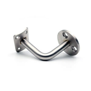
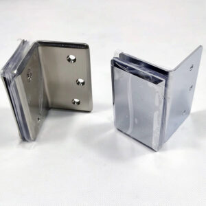
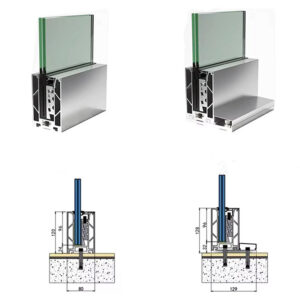
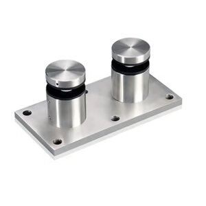
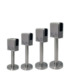
Mounting Methods: Surface-Mount vs. Fascia-Mount Post Systems
Structural and Aesthetic Implications of Mounting Choice
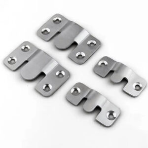
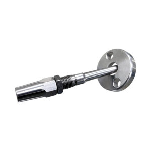
The attachment method determines the railing’s visual relationship with the deck structure. Surface-mount systems use a flanged base plate secured directly to the deck framing, offering robust strength and straightforward installation. Fascia-mount systems attach to the side of the band joist, preserving a clean deck surface without penetrations. This is not merely a cosmetic decision; the choice affects load path and requires careful consideration of the underlying structure’s ability to handle lateral forces.
Cost and Installation Trade-Offs
Easily overlooked details include the direct cost implication and long-term accessibility. Pricing analysis reveals fascia-mounted posts are consistently 6-12% more expensive due to added bracketry and hardware. Furthermore, fascia-mount installations can complicate future maintenance or repair access to the deck’s rim joist. For project specifiers, this represents a clear trade-off: surface-mount offers cost-effective strength, while fascia-mount delivers a premium, streamlined aesthetic at a higher installed cost.
The cost and characteristic differences between mounting methods are summarized below:
| Mounting Method | Key Characteristic | Cost Implication |
|---|---|---|
| Surface-Mount (Deck-Mount) | Flanged base plate | Lower installed cost |
| Fascia-Mount (Side-Mount) | Bracket on band joist | 6-12% more expensive |
| Surface-Mount | Direct to deck framing | Robust strength |
| Fascia-Mount | Clean deck surface | Preserves board overhang |
Source: Technical documentation and industry specifications.
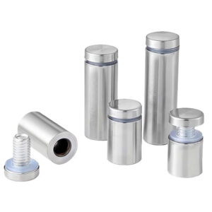
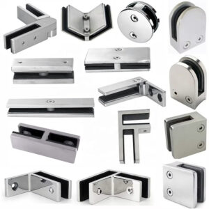
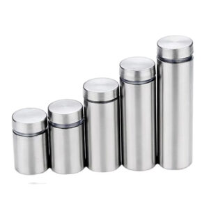
Integrating Cable Infill: Thru-Post vs. Fitting-Based Systems
The Pre-Drilled vs. Custom Drilling Decision
Cable integration defines the installation workflow. Thru-post systems with pre-drilled holes ensure code-compliant spacing (typically 3 inches on-center) and allow for continuous cable runs, accelerating installation. Vendors offer identical post models in both pre-drilled and un-drilled versions, with pre-drilled commanding a ~10-15% premium. Un-drilled posts offer ultimate flexibility for custom cable spacing but introduce the risk of error during on-site drilling. In my experience, the labor cost of precise field drilling often negates the savings from buying un-drilled posts on standard layouts.
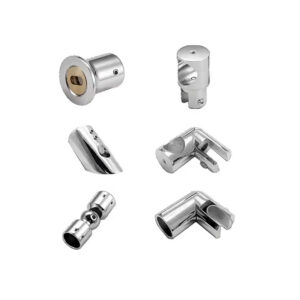
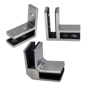
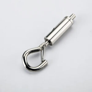
Hardware-Based Termination Methods
Fitting-based systems terminate cables at each post using external clamps or connectors. This method allows for easy replacement of individual cable sections and can accommodate complex layouts where continuous runs are impossible. However, it introduces more hardware points that require inspection and can create a busier visual profile. The choice between continuous runs and discrete segments hinges on design complexity, maintenance planning, and visual preference.
The procurement and functional trade-offs are clear:
| System Type | Key Feature | Cost/Premium |
|---|---|---|
| Thru-Post (Pre-Drilled) | Continuous cable runs | ~10-15% premium |
| Thru-Post (Pre-Drilled) | Ensures code spacing | Accelerates installation |
| Fitting-Based | External termination hardware | Custom spacing possible |
| Thru-Post (Un-Drilled) | Requires on-site drilling | Maximum layout flexibility |
Source: Technical documentation and industry specifications.
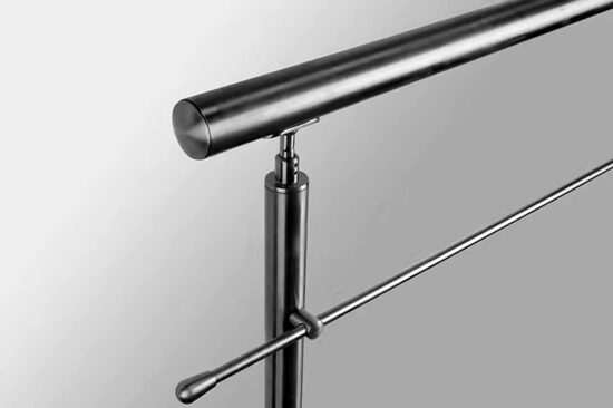
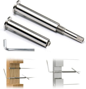
Tensioning Hardware and Procedures for a Safe, Rigid Railing
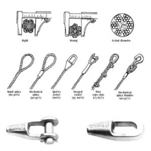
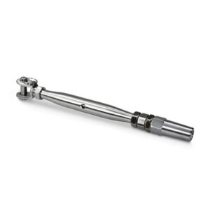
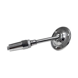
Achieving and Measuring Proper Tension
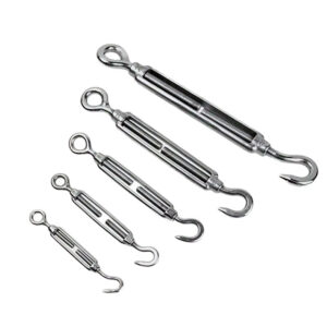
A cable railing’s rigidity comes from uniform tension, typically between 75-125 pounds per cable. This is achieved with hardware housed within terminal posts, such as turnbuckles or proprietary inline tensioners. The anchor point for this hardware must be integral to the post’s structure, often a through-bolt or welded nut plate. Using a tension gauge is not optional; it is required to achieve uniformity and verify the design load. Sequential tensioning—starting from the middle of a run and working outward—prevents uneven load distribution and post deflection.
Accounting for Cable Creep and Long-Term Performance
All cables experience initial creep (stretching), necessitating a re-tensioning cycle within 30-90 days of installation. This manual process is skill-dependent, creating a latent demand for integrated tension-measuring solutions. Strategic suppliers differentiate by offering systems with verifiable load documentation, reducing installer liability. This procedural requirement shifts the focus from mere component supply to providing a complete performance system.
Key parameters for the tensioning process are standardized:
| Parameter | Specification/Range | Key Tool/Process |
|---|---|---|
| Target Cable Tension | 75-125 lbs | Tension gauge required |
| Initial Re-tensioning | Within 30-90 days | Addresses cable creep |
| Tensioning Hardware | Turnbuckle or inline tensioner | Housed in terminal post |
| Tensioning Sequence | Middle outward | For uniformity |
Source: Technical documentation and industry specifications.
Key Building Code Requirements for Residential and Commercial Decks
Height and Infill Opening Mandates
Compliance with the International Residential Code (IRC) and International Building Code (IBC) is mandatory. Minimum railing height is 36 inches for residential decks and 42 inches for commercial applications or residential decks over 30 inches high. The infill must prevent a 4-inch sphere from passing through any opening, which standard 3-inch cable spacing addresses. These are absolute minimums; local amendments may impose stricter requirements, making a preliminary jurisdiction check essential.
Structural Load Requirements
The code mandates that the railing system must resist a concentrated load of 200 pounds applied in any direction and a uniform load of 50 pounds per linear foot. These loads are transferred to the deck structure through the posts and their attachments. The IBC International Building Code Chapter 16 Structural Design establishes these minimum design loads, requiring that posts, connections, and anchoring be engineered accordingly. This makes professional design review non-negotiable for complex or commercial installations.
The code distinctions are summarized in this table:
| Requirement | Residential (IRC) | Commercial (IBC) |
|---|---|---|
| Minimum Railing Height | 36 inches | 42 inches |
| Infill Openings (Max) | 4-inch sphere rule | 4-inch sphere rule |
| Concentrated Load | 200 lbs | 200 lbs |
| Uniform Load | 50 lbs/ft | 50 lbs/ft |
Source: IBC International Building Code Chapter 16 Structural Design. This code chapter establishes the minimum structural load requirements (concentrated and uniform) that guardrail systems and their posts must be designed to resist for safety compliance.
Post Spacing, Layout, and Structural Load Considerations
Determining Maximum Span Between Posts
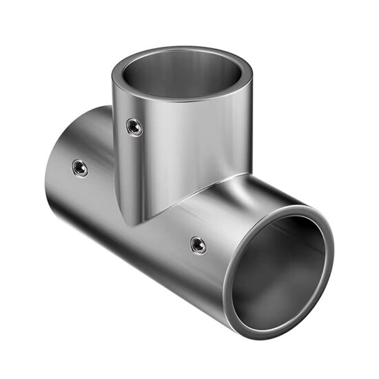
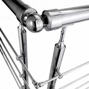
Post spacing is governed by structural calculations based on top rail strength and required load resistance, but typically does not exceed 4 to 6 feet for stainless systems. Closer spacing may be required for taller railings, high-wind areas, or when using lighter gauge materials. The layout must accurately identify every terminal (load-bearing) and intermediate (non-tension) post; misclassification is a critical safety error. Corner posts and stair posts require specialized planning to manage multi-directional loads and angled cable runs.
Navigating Logistics and Procurement Sequencing
A hidden complexity lies in supply chain logistics. Standard components like fittings and posts often ship via parcel carriers, while long items like top rails typically ship via freight. This creates disparate delivery timelines, from 1-5 days for parcels to up to 30 days for freight. Project managers must sequence procurement around this reality, splitting orders if necessary, to avoid costly delays waiting for a single component. Meticulous coordination during the specification phase prevents timeline disruptions.
These practical considerations impact project flow:
| Consideration | Typical Specification | Impact/Note |
|---|---|---|
| Maximum Post Spacing | 4 to 6 feet | For stainless systems |
| Component Shipment (Standard) | Parcel carrier | Faster delivery (e.g., 1-5 days) |
| Component Shipment (Long Rails) | Freight carrier | Slower delivery (e.g., up to 30 days) |
| Layout Planning | Identify terminal posts | Critical for safety |
Source: Technical documentation and industry specifications.
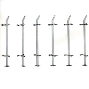
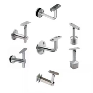
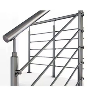
Selecting Between Terminal, Intermediate, and Specialized Post Types
The Functional Hierarchy of Post Components
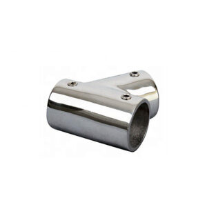
Selecting the correct post type is foundational. Terminal/Tension posts are used at ends and corners to anchor cables. Intermediate/Line posts provide guidance and spacing between terminals. Specialized types include Corner posts, which manage tension from two angles, and Stair posts (upper and lower), which are drilled at an angle to keep cables parallel to the stair rake. This component modularity allows for extensive customization but creates a complex specification process. Suppliers must provide clear configuration tools to prevent error.
Ensuring Compatibility in a Modular System
The array of compatible parts demands mastery from installers. A terminal post requires a reinforced structure and proper hardware mounting points, which differ from an intermediate post. Using an intermediate post in a terminal position will lead to system failure. Similarly, stair posts are not interchangeable with standard posts. Understanding this functional hierarchy and ensuring all components are designed to work together within a single engineered railing system is essential for both structural integrity and intended aesthetics.
Maintenance, Long-Term Care, and Re-Tensioning Schedules
Establishing a Proactive Maintenance Regimen
Long-term performance extends beyond installation. After the initial 30-90 day re-tensioning, cables may need periodic adjustment, especially in environments with significant thermal cycling. Corrosion protection is also critical; regular cleaning with non-abrasive, pH-neutral cleaners is recommended to maintain the passive oxide layer on the stainless steel. For harsh environments, more frequent cleaning may be necessary to remove chlorides and pollutants.
The Strategic Shift to Prescribed Care Systems
Leading suppliers now bundle specialized care products—passivators, rust removers, epoxy repair kits—alongside hardware. This transforms maintenance from a generic recommendation into a prescribed, brand-specific regimen. This practice protects brand reputation against corrosion failures, reduces warranty claims, and creates a recurring revenue stream. It represents a quality-focused strategy that appropriately shifts some long-term performance responsibility to the owner while providing them with the correct tools for the job.
The success of a stainless steel cable railing installation hinges on three priorities: accurate post specification based on structural role, adherence to a meticulous tensioning and re-tensioning protocol, and a clear understanding of the logistical realities of component procurement. Treating the system as an integrated assembly, not a collection of parts, is what separates a compliant installation from an exceptional one.
Need professional guidance to navigate these specifications for your next deck or commercial project? The experts at Esang provide the engineering support and high-quality components required to execute these complex systems with confidence. For direct inquiries regarding your specific design challenges, you can also Contact Us.
Frequently Asked Questions
Q: What are the key material specifications for stainless steel cable railing posts to ensure structural integrity?
A: The primary specification is the stainless steel grade and tubing wall thickness. For harsh environments like coastal areas, Type 316/L marine-grade is standard, while Type 304/L is suitable for general use. The posts themselves are typically fabricated from welded stainless steel mechanical tubing, which must meet quality standards like ASTM A554. This means projects in corrosive environments must specify the higher-grade material and verify tubing certifications to prevent premature failure and ensure long-term safety.
Q: How do you choose between surface-mount and fascia-mount posts for a deck project?
A: The choice balances structural needs, aesthetics, and budget. Surface-mount systems bolt directly to the deck framing for maximum strength and simpler installation. Fascia-mount systems attach to the side of the band joist, preserving a clean deck surface but requiring more complex hardware, which typically increases cost by 6-12%. For projects where a seamless deck finish is a priority, you should plan for the higher material cost and potential complexity of integrating the side-mounted brackets with the building envelope.
Q: What is the practical difference between thru-post and fitting-based cable systems for procurement and installation?
A: Thru-post systems use pre-drilled holes for continuous cable runs, ensuring consistent, code-compliant spacing but limiting layout flexibility. Fitting-based systems use external hardware at each post, allowing for custom cable spacing. Vendors often charge a 10-15% premium for pre-drilled posts. This means standard layouts benefit from the speed of pre-drilled components, while custom designs with unique spacing require the flexibility of un-drilled posts and precise on-site labor, directly impacting both material costs and installation timeline.
Q: What building code loads must stainless steel cable railing posts be designed to resist?
A: Posts and their attachments must be engineered to resist a concentrated load of 200 pounds or a uniform load of 50 pounds per linear foot, as stipulated by model codes like the IBC. These structural requirements make professional design review essential, especially for commercial applications or complex installations. If your project involves high decks or public spaces, you must verify that the post specifications and mounting method are calculated to meet these minimum load criteria.
Q: How does the function of terminal posts differ from intermediate posts, and why does it matter for specification?
A: Terminal (or tension) posts anchor the cable runs and house the tensioning hardware, requiring heavier construction (e.g., 10-gauge) to withstand concentrated tensile loads. Intermediate (or line) posts merely guide the cables and can use lighter gauge material (e.g., 12-gauge). This functional bifurcation is foundational to system safety. For specifiers, accurately classifying each post location in the layout is non-negotiable to avoid the safety risk and cost of using an under-specified post at a critical tension point.
Q: What maintenance is required for stainless steel cable railings after installation?
A: A proactive regimen includes an initial re-tensioning of cables within 30-90 days to account for creep, followed by periodic adjustments, especially in climates with significant temperature swings. Corrosion protection involves regular cleaning with non-abrasive, appropriate products. This long-term performance requirement means facility managers should establish a scheduled inspection and maintenance plan, and consider suppliers who offer compatible care products to ensure proper upkeep and protect the system’s lifespan.
Q: What are the critical steps for proper cable tensioning during installation?
A: Achieving a safe, rigid railing requires tensioning cables to 75-125 lbs using a calibrated gauge for uniformity. The hardware, like a turnbuckle, must be anchored to a structurally reinforced point within the terminal post. The procedure typically involves sequential tensioning from the middle outward. This skill-dependent process means installers should use proper tools and document tension values; for high-liability projects, plan to use systems with integrated tension-measuring features to provide verifiable proof of compliance.