A cable railing assembly can fail to perform not because the tensioner is undersized, but because it was matched to the wrong cable. Two cables with the same nominal diameter can differ in strand construction and end preparation, and those differences decide whether a given terminal can grip the cable without slippage or damage. Before comparing tensioner models, the question is whether the specific cable on hand has been identified closely enough to check against the tensioner’s actual requirements.
Cable Inputs Needed Before Tensioner Selection
| Cable input | Project-specific detail to record | Selection relevance |
|---|---|---|
| Actual cable designation | Exact designation for the cable being used | Prevents selection from relying only on a nominal diameter label |
| Supplier data | Data supplied for the identified cable | Provides the part-specific basis for checking compatibility |
| Cable diameter | Actual diameter information for the identified cable | Must be considered together with strand construction and end preparation |
| Strand construction | Construction of the identified cable | Affects whether the selected terminal can grip the cable without damage |
| End preparation | Preparation specified for the cable end | Affects whether the selected terminal can grip the cable without damage |
Selecting a tensioner starts with identifying the cable, not the tensioner. A nominal diameter label describes a target dimension, but manufacturing tolerances, strand construction, and core type all affect the cable’s actual behavior inside a terminal. Two cables sold under the same nominal diameter can present different effective diameters or different surface characteristics where the terminal makes contact, and a terminal sized to one may not seat correctly on the other.
This is why the actual cable designation and the data supplied for that specific cable take precedence over a general diameter figure. The designation identifies the construction family and the source the buyer can return to if a question arises about tolerance or finish. Supplier data for that identified cable gives the buyer something to check against the tensioner manufacturer’s stated requirements, rather than relying on an assumption that any cable at a given diameter will behave the same way inside the grip mechanism.
Where the buyer is sourcing cable and tensioner from different points in the supply chain, this step carries more weight, because there is no shared assumption between the two suppliers about what construction or preparation will arrive on site. Where cable and tensioner are specified together as part of one system, the designation and supplier data still need to be recorded, because later questions about a damaged terminal or a loose grip are easier to resolve when the original cable identity was captured at selection rather than reconstructed afterward from a diameter label alone.
Recording this information does not yet answer whether the tensioner will grip the cable correctly. It establishes the basis the buyer needs to evaluate that question, because strand construction and end preparation, considered next, determine the terminal’s actual compatibility with the cable in hand, not just its nominal size.
Diameter Versus Strand Construction and End Preparation
Diameter sets an envelope, but it does not by itself determine whether a terminal will grip a cable without damage. Strand construction affects how the cable behaves under compression or swaging: a cable built from more, finer strands compresses differently than one built from fewer, heavier strands, even where both report the same nominal diameter. A terminal designed around one construction can crush, distort, or fail to fully engage a cable with a different internal geometry, even if the cable passes through the terminal’s bore without resistance.
End preparation changes this picture again. How the cable end is cut, whether it is seized or otherwise prepared before it enters the terminal, and whether any preparation step is specified by the terminal manufacturer all affect whether the terminal can seat and grip as intended. A terminal that assumes a particular end preparation will not necessarily perform the same way on a cable end prepared differently, even when diameter and strand construction both match.
This is where diameter alone becomes an unreliable filter. Where two cables share a nominal diameter but differ in strand construction or end preparation, a tensioner cleared for one does not automatically clear for the other. The buyer’s task is to treat diameter as one input among several, not as the single qualifying figure, and to confirm strand construction and end preparation against what the tensioner manufacturer specifies for that terminal design.
Where the project allows the installer to select or confirm end preparation before terminals are fitted, that preparation should be set to match the terminal’s documented requirement rather than left to a default practice carried over from a different cable or a different tensioner family. Where end preparation has already been fixed upstream, before the tensioner is chosen, the sequence reverses: the tensioner selection must accommodate the preparation already present on the cable, and that constraint narrows which terminal designs remain viable.
Swaged and Swageless Grip Boundaries
Swaged and swageless terminals grip cable through different mechanisms, and that difference carries directly into which cable constructions and end preparations each can accept. A swaged terminal relies on a permanent mechanical deformation applied to the terminal around the cable, so its holding capacity depends on the swaging process matching the cable’s actual diameter and construction at the time of swaging. A swageless terminal relies on an internal mechanical grip, typically set and adjusted without a swaging step, and its holding capacity depends on the cable seating correctly within that mechanism without being crushed or allowed to slip.
Because these mechanisms work differently, the boundary between what each can accept is not interchangeable. A cable construction or end preparation suited to a swaging process will not automatically suit a swageless mechanism’s grip geometry, and the reverse also holds. Where a project substitutes one terminal type for the other without re-checking construction and end preparation against the new terminal’s requirements, the earlier compatibility work done for the original terminal does not carry over.
This is also where named-instruction accuracy matters most. Swaged and swageless terminals from different manufacturers, or different models from the same manufacturer, can specify different acceptable cable constructions and end preparations even where both terminals are nominally rated for the same diameter range. The buyer’s task is not to classify a cable as generically compatible with “swaged” or “swageless” hardware, but to confirm the specific terminal’s instructions against the specific cable’s designation, construction, and end preparation already on record. Where that confirmation has not been done, diameter compatibility alone does not establish that the terminal will grip the cable as intended.
Thread Terminal and Post Interface Matching
| Interface check | Project-specific value to confirm | Matching boundary |
|---|---|---|
| Thread size and hand | Thread size and hand for the selected parts | Must match the opposing end fitting within the named assembly |
| Terminal geometry | Geometry of the selected terminal and mating parts | Must match the post interface and opposing end fitting as one assembly |
| Usable travel | Usable travel of the selected tensioner | Must suit the selected parts as one named assembly |
| Post interface | Interface of the selected post and terminal | Must match the terminal geometry within the named assembly |
| Opposing end fitting | Exact fitting selected for the other end | Must be confirmed with the tensioner rather than treated as an independent part |
Once the cable side of the assembly is settled, the opposite side introduces its own matching requirements. A tensioner connects to a post or structural member through a defined interface, and it connects to an opposing end fitting through a threaded connection. Each of these connections carries its own geometry, and none of them can be assumed compatible just because the tensioner and the opposing parts share a general product family or finish.
Thread size and hand determine whether a tensioner’s threaded terminal will engage an opposing end fitting at all. A mismatch in thread size prevents engagement outright; a mismatch in hand allows the threads to appear to start before binding or failing to draw up correctly. Terminal geometry extends this concern beyond the threads themselves, covering how the terminal body interfaces with the post fitting or structural connection point, which can vary even among terminals that share a thread specification.
Usable travel affects whether the tensioner can actually take up the slack the installation requires. A tensioner with limited adjustment range may thread correctly onto the opposing fitting yet lack the travel needed to reach proper tension once the cable run and post spacing are fixed. This makes usable travel a property of the assembly as installed, not a fixed attribute of the tensioner considered alone.
The post interface itself is the final link, and it must match both the terminal geometry on the tensioner side and whatever fitting is used at the post. Where the post hardware was specified independently of the tensioner, this interface deserves direct confirmation rather than an assumption that generic stainless hardware will align.
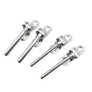
Esang’s cable tensioner systems and swageless cable tensioners, along with threaded cable end fittings, illustrate why these checks apply to a named combination of parts rather than to a category of hardware. A thread specification on one tensioner does not establish what will be true of a different tensioner in the same product line, and an opposing end fitting selected for appearance or finish still needs its thread size, hand, and geometry confirmed against the specific tensioner it will be paired with.
Named-Assembly Confirmation Before Release
| Evidence to check | What it supports | What it does not establish |
|---|---|---|
| Actual cable designation and supplier data | Identification of the cable used for the compatibility check | Compatibility based only on a nominal diameter label |
| Named tensioner’s assembly instructions | Part-specific instructions for the selected tensioner assembly | Compatibility of a different combination of parts |
| Confirmed thread size and hand, terminal geometry, usable travel, post interface, and opposing end fitting | Matching the selected parts as one named assembly | An unconditional conclusion for other configurations |
| ISO 2408:2017 within its stated product scope | Requirements for steel wire ropes covered by the standard | Tensioner capacity, post spacing, or cable-railing system compliance |
The cable identification, construction and end-preparation checks, and interface matching converge on a single question before any assembly is released for installation: do the specific parts selected, as a named combination, meet the manufacturer’s instructions for that combination. This is a narrower question than whether each part individually meets a general specification.
A wire-rope standard such as ISO 2408:2017 establishes requirements for steel wire ropes within its own stated product scope. That scope covers the cable as a manufactured product; it does not extend to tensioner capacity, post spacing, or compliance of the assembled cable-railing system. Confirming that a cable meets this standard answers a question about the cable itself. It does not answer whether a particular tensioner will grip that cable correctly, or whether the completed railing assembly meets whatever performance expectation the project has set. Treating wire-rope compliance as a stand-in for assembly compliance conflates two different scopes of evidence.
The information a buyer can rely on for release is narrower and more specific: the actual cable designation and supplier data identified earlier, the named tensioner’s own assembly instructions, and confirmation that thread size and hand, terminal geometry, usable travel, post interface, and opposing end fitting all match as one assembly. Each of these supports a conclusion about the specific parts checked. None of them, individually or together, extends automatically to a different combination of parts, even one that looks similar on paper.
Where the project has gathered this evidence for one named assembly, that evidence supports release of that assembly. Where the project substitutes a different cable, a different tensioner, or a different opposing fitting, the prior confirmation no longer applies, and the same sequence of checks needs to be repeated for the new combination. This is the distinction that separates a project-specific release decision from a general assumption about product-line compatibility, and it is the reason the cable designation, supplier data, and named instructions need to be kept together as project records rather than treated as a one-time check that applies to future orders by default.
Frequently Asked Questions
Q: Can a cable tensioner be selected from the cable’s nominal diameter alone?
A: No. Record the actual cable designation, supplier data, diameter, strand construction, and end preparation, then check that complete information against the named tensioner’s assembly instructions.
Q: How should I decide whether a swaged or swageless tensioner fits the cable?
A: Check whether the selected terminal’s specified grip method accepts the identified cable construction and end preparation without damage. Treat the decision as part-specific rather than assuming that every swaged or swageless terminal fits cable with the same nominal diameter.
Q: What must be matched after cable compatibility is confirmed?
A: Confirm the thread size and hand, terminal geometry, usable travel, post interface, and opposing end fitting together as one named assembly. A compatible cable-to-terminal connection does not by itself confirm that these remaining interfaces fit.
Q: What information should be ready before the assembly is released for purchase or fabrication?
A: Prepare the exact cable designation and supplier data, the named tensioner’s assembly instructions, and confirmed values for every mating interface. Keep the selected part combination explicit so evidence for one configuration is not applied to another.
Q: Does ISO 2408:2017 establish that the complete cable-railing assembly is suitable?
A: No. It supports requirements for steel wire ropes within its stated product scope; it does not establish tensioner capacity, post spacing, or cable-railing system compliance. Those points require separate project-specific confirmation.