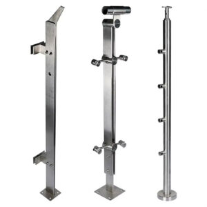
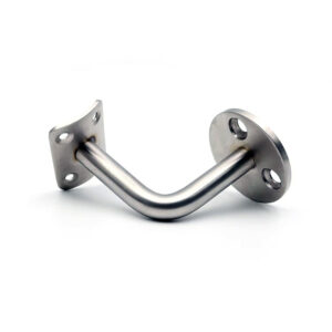
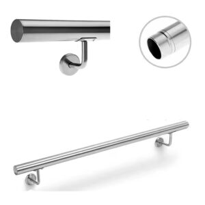
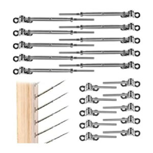
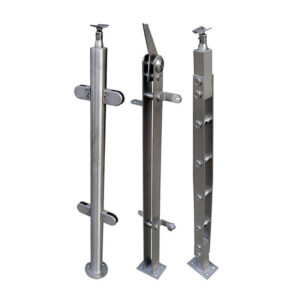
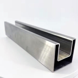
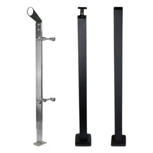
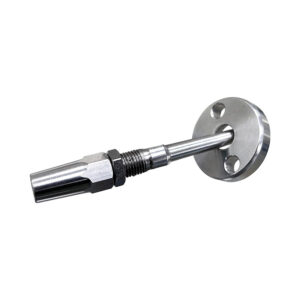
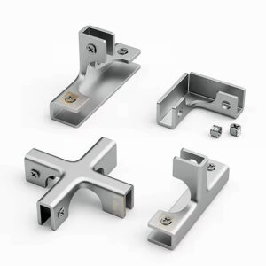
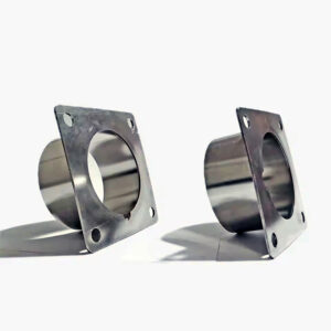
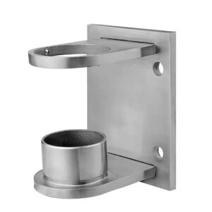
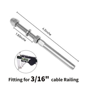
Selecting a plate that fits the post is a routine step. What breaks projects is the assumption that post compatibility is sufficient—and the concrete damage, anchor installation failures, and inspection gaps that follow when the anchor group and substrate were never part of the selection. On commercial sites, the consequence is rarely visible until the slab is poured, the anchors are set, and a field crew discovers there is no room to torque a nut or that the hole pattern has landed inside the rebar cage. Remediation at that stage means core drilling, epoxy injection, or structural review under time pressure. The judgment that avoids this is treating the plate, anchors, and substrate as one coordinated load path from the moment the drawing reaches the submittal desk.
Base Plate Anchor and Post as One Load Path
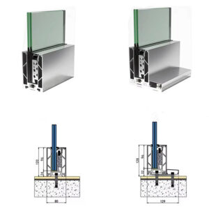
A surface-mounted base plate does not simply hold a post upright—it transfers horizontal railing loads into the supporting structure through a moment couple. When a guardrail post is pushed laterally, the plate simultaneously bears in compression against the concrete on one side and pulls its anchors into tension on the other. That mechanism only works reliably when all four components—post section, plate geometry, anchor group, and concrete substrate—are designed together to carry the same load in the same direction.
The failure pattern that recurs on commercial projects is plate selection that stops at post compatibility. A plate is matched to the post base dimension, a standard anchor pattern is applied, and the drawing moves forward without anyone verifying that the anchor embedment matches the plate’s assumed tension demand, or that the concrete’s edge distance supports the breakout resistance the calculation assumes. The load path looks complete on the drawing because all the parts are present. It is only incomplete in the relationship between them.
ASTM E894-88(2004) addresses anchorage performance for permanent metal railing systems, and ASTM E985-24 covers system-level requirements for guardrails—both provide direct grounding for why the anchorage connection must be treated as a structural interface rather than a hardware selection. The moment-couple model is the design figure that explains how surface-mounted plates work; project-specific conditions, particularly substrate strength, edge distances, and anchor configuration, determine whether the path performs as assumed.
Each component in that path carries a defined role, and a mismatch at any point breaks the chain.
| Load Path Component | Role in Moment Couple | What Must Be Coordinated |
|---|---|---|
| Railing Post | Transmits horizontal railing load to the base plate connection | Post section and connection strength must match the design moment |
| Base Plate | Delivers compression to concrete and houses anchor bolts | Plate dimensions, thickness, and hole pattern must suit anchor layout and concrete bearing capacity |
| Anchor Group | Resists tensile force from the moment couple | Anchor size, embedment, edge distance, and spacing must align with plate holes and substrate capacity |
| Concrete Substrate | Provides compression reaction and breakout resistance | Concrete strength, reinforcement, and edge distance assumptions must be verified for anchor breakout and plate bearing |
The coordination failure that is hardest to catch in review is not missing information—it is information that is present but unchecked against adjacent components. A plate thickness that suits the post may still be undersized for the anchor layout it houses. An anchor group that satisfies tension demand in isolation may still fail concrete breakout if the edge distance assumptions in the calculation do not match what was actually built. Treating these as sequential decisions rather than a single coordinated load path is the structural equivalent of approving each link in a chain without checking whether they connect.
Hole Crowding and Concrete Damage Risks
A hole pattern that looks adequate in a shop drawing can translate into serious installation and structural problems once field conditions are factored in. The risk is not the hole size—it is the cumulative effect of anchor spacing, slab edge proximity, and rebar location on the concrete’s actual capacity to resist breakout and on the crew’s ability to install anchors correctly.
The chain of decisions that produces this failure is predictable. A compact plate is selected to minimize visual footprint. The anchor pattern is laid out to fit within the plate boundary. No one checks whether the distance from the outermost hole to the slab edge satisfies the design assumption, or whether the hole layout conflicts with existing reinforcement. On site, the crew drills to the drawing and discovers either that a rebar is in the way or that the distance from hole center to slab edge leaves clearance measured in millimeters—not enough to install and torque the anchor without damaging the concrete edge. When edge reinforcement must be cut or relocated to allow drilling, the concrete’s breakout capacity decreases further, and that change is rarely reflected in the original calculations.
The 20 mm clearance scenario documented in published guidance is an illustrative extreme, not a standard threshold. But it demonstrates how a layout that appears constructable in plan can become structurally compromised and physically unworkable once tolerance, rebar position, and anchor installation geometry are accounted for simultaneously. The planning decision that prevents this is verifying hole layout against all three constraints—edge distance per design, rebar coordination, and installation clearance—before the drawing is approved, not after the slab is poured.
Each of these risk factors carries a specific consequence that connects the layout decision to the structural outcome.
| Risk Factor | Potential Consequence | What to Confirm |
|---|---|---|
| Insufficient edge distance | Reduces concrete breakout capacity; can lead to concrete edge failure | Confirm minimum edge distance per design and check actual tolerance with slab edge |
| Interference with edge reinforcement | May require elimination of reinforcement, further reducing breakout capacity | Coordinate hole layout with rebar locations; verify any reinforcement removal is accounted for in the design |
| Hole pattern too close to slab edge | Leaves minimal clearance for anchor installation and tightening (e.g., only 20 mm) | Confirm that the hole layout provides adequate working clearance and constructability |
The harder problem is that hole crowding is often introduced gradually. A plate is upsized slightly to gain stiffness, which pushes the outer anchors closer to the edge. Or a post is repositioned for aesthetic alignment, shifting the plate toward the slab perimeter. Each individual decision seems minor. The aggregate effect is a layout that the original breakout calculation no longer covers—and that fact surfaces only when field crews flag the problem or, in the worst case, when the anchor fails under load.
Plate Stiffness Versus Visual Footprint
Plate thickness and plan dimensions are the two variables that control stiffness, and both of them directly affect what the plate looks like from ground level. A thicker, wider plate distributes load more effectively across the anchor group and provides more working room for hole layout. It also creates a larger, more prominent base condition that architects and owners on commercial projects often push back on. That conflict is real and does not resolve cleanly in either direction.
The structural case for a stiffer plate is not about aesthetics—it is about the reliability of the moment-couple transfer. A plate that flexes under load shifts the compression reaction and changes the effective lever arm between anchor tension and concrete bearing. Depending on the load magnitude and substrate stiffness, this may reduce the actual capacity below what the calculation assumes. The effect is more pronounced on weaker substrates or at longer post heights where the applied moment is larger. A plate that performs adequately on a thick concrete slab at a low post height may not be suitable on a thinner substrate with the same visual footprint.
The trade-off is not that a smaller plate is always unsafe—it is that the engineering basis for a compact plate depends on conditions that vary by project. Reducing plate size to meet a visual brief requires confirming that the reduced anchor layout still satisfies edge distance requirements, that the thinner plate can be shown to deliver the required bearing, and that the hole pattern remains constructable. If those checks are not carried, the visual preference is being prioritized over an unverified structural assumption. The balance point depends on load, substrate, and layout—not on a fixed footprint ratio.
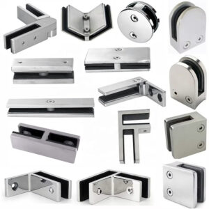
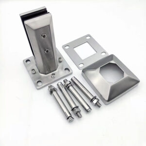
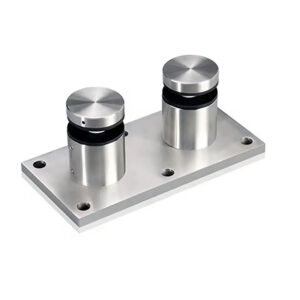
For projects where load and substrate conditions support a more compact profile, surface mount base plates offer a lower visual profile while maintaining the structural connection geometry required for proper load transfer. Where higher loads, edge proximity, or difficult substrates demand more robust anchorage geometry, heavy duty base plates provide the plate dimensions and thickness needed to support a verified load path. The decision between them should follow the engineering, not the elevation drawing.
Cover Plates and Lost Inspection Access
Cover plates are added for a reason that is visually obvious: they conceal the anchor hardware and weld details at the base of a guardrail post, producing a clean finish at floor level. The problem is that they also conceal the connection permanently—and a connection that cannot be inspected cannot be confirmed to be functioning as designed.
This matters over time in a way that is easy to underestimate during installation. Anchor corrosion, weld cracking, or grout deterioration beneath a cover plate cannot be detected without removal. On commercial projects where the guardrail carries occupant loads for the life of the building, the inability to verify anchor integrity on a routine basis is not a minor inconvenience—it is an enduring inspection gap. If the cover plate is sealed in place with adhesive or set into a finished floor condition, removal for inspection may require damage to the surrounding finish, which in practice means the inspection does not happen.
The additional risk is documentation timing. Cover plates are often installed immediately after the post is set, before inspectors or maintenance teams have recorded the anchor specification, torque values, weld details, or plate thickness. Once the plate is in place, the connection exists only as a drawing reference. If that drawing is incomplete—if it omits plate thickness, weld specification, or anchor layout—the installed condition is unverifiable and the design basis is essentially undocumented for the life of the structure.
The decision to use a cover plate is not inherently wrong. But it should be made with a clear understanding that it forecloses future visual access to the connection. Projects that accept cover plates as a finish detail should record the anchor installation—torque values, embedment confirmation, weld inspection results—before the plate is set. That documentation becomes the only lasting evidence of what is behind the cover.
Drawing Checks Before Base Plate Approval
The submittal drawing is the last point at which errors in plate geometry, anchor layout, and substrate assumptions can be caught without field consequence. Once the drawing is accepted and work proceeds, any omission in the connection details is effectively locked into the structure. The review function is not administrative—it is the mechanism by which load-path compatibility, concrete capacity, and inspection access are confirmed before they become unalterable.
The verification logic follows from the project’s structural hierarchy. A delegated designer produces sealed shop drawings and supporting calculations, but that delegation does not transfer responsibility for consistency with the overall building design. The engineer of record’s review ensures that the plate geometry, anchor sizing, and substrate assumptions in the submittal align with the structural conditions defined in the contract documents—concrete strength, reinforcement layout, edge distances, and load magnitude. Where those project-specific conditions are not explicitly referenced in the submittal, the review cannot confirm alignment, and the accepted drawing carries implicit assumptions that may not reflect what was actually built.
The specific items that recur as gaps in incomplete submittals are predictable: plate thickness is noted as a nominal dimension without the calculation basis; weld specifications are shown as symbols without throat size or procedure reference; anchor layout is confirmed in plan but not checked against edge distance tolerances or rebar coordination drawings; and inspection access after cover plate installation is not addressed at all. Each omission is individually minor in the review. Together, they describe a connection whose design basis cannot be fully reconstructed from the record documents.
ASTM E894-88(2004) and ASTM E985-24 provide the anchorage performance and railing system standards that submittal calculations must address. They are the technical reference frame within which the load-path verification sits. The submittal review is the project-specific confirmation that the design meets those standards under the actual field conditions.
| Submittal Item | Why It Matters | What to Confirm |
|---|---|---|
| Sealed shop drawings from delegated designer | Establishes design responsibility; shows plate geometry, welds, and holes | Verify seal and that drawings show plate thickness, anchor layout, and access for inspection |
| Calculations | Supports load path, anchor capacity, and concrete breakout design | Confirm calculations address load direction, edge distances, reinforcement assumptions, and concrete strength |
| Engineer of Record (EOR) review | Ensures load path and structural support are consistent with overall building design | Verify EOR has reviewed and marked the submittal as accepted or approved |
| Project-specific conditions in contract documents | Edge distances, reinforcement assumptions, and concrete strength directly affect design validity | Confirm that the submittal references the same values specified in the contract documents |
An accepted submittal that is missing any of these items does not become complete through acceptance—it becomes an approved gap. The correction is to define what the submittal must contain before it is submitted, not to identify what it was missing after installation is underway. For guidance on how mounting hardware submittals fit into broader commercial and industrial project documentation, the Complete Stainless Steel Mounting Hardware Guide provides relevant selection and documentation context.
The most consistent source of base plate problems on commercial guardrail projects is a selection process that treats the plate as an isolated component rather than as one node in a load path that includes the post, the anchor group, and the concrete substrate. Hole crowding, reduced breakout capacity, cover plate concealment, and incomplete submittal drawings are not independent failures—they are downstream consequences of that same upstream assumption.
Before approving a base plate selection, confirm that the drawing shows plate thickness, weld specification, anchor layout with edge distances, substrate assumptions, and inspection access. If any of those items is missing, the structural basis for the connection is incomplete regardless of how the rest of the drawing looks. That confirmation is not a formality—it is the only point in the project at which the full load path can still be corrected before it is set in concrete.
Frequently Asked Questions
Q: What if the concrete slab is already poured and I’m retrofitting guardrails—can I still use surface-mounted base plates?
A: Yes, but selection must begin with field verification of existing edge distances, concrete strength, and reinforcement location. The load-path coordination described in the article assumes new construction where these conditions can be set in drawings. On retrofits, use exploratory drilling or GPR scanning to confirm the slab can meet the anchor group’s breakout and edge-distance requirements before finalizing the plate layout.
Q: After the base plate submittal is approved, what should the installer check immediately after drilling anchor holes but before setting the plate?
A: Verify the as-drilled hole positions against the design edge distances, rebar conflicts, and anchor installation clearance. The article shows that compact layouts can land too close to slab edges or hit reinforcement, silently reducing breakout capacity. Recording these measurements before the plate is set is the last practical chance to catch a layout that no longer matches the structural assumptions.
Q: At what point does a compact surface-mounted base plate become structurally insufficient, requiring a heavy-duty plate instead?
A: A compact plate becomes insufficient when the moment demand cannot be supported without violating the required edge distance or exceeding the concrete’s breakout strength. This typically occurs with taller guardrail posts, thin slab substrates, or high lateral loads. If the anchor group layout needed for the load pushes too close to a free edge or requires a plate thickness beyond the compact profile, switching to heavy duty base plates with larger plan dimensions and greater stiffness restores a verifiable load path.
Q: When should I specify surface-mounted base plates instead of using embedded posts?
A: Choose surface-mounted base plates when cast-in posts are impractical due to forming constraints, when post locations may need adjustment after concrete placement, or when future reconfiguration is expected. Embedded posts eliminate base plate inspection concerns but lock the layout into the pour. Surface-mounted plates offer flexibility but demand the kind of coordinated anchor, substrate, and plate selection this article describes.
Q: Are cover plates worth the risk of losing inspection access over the life of the guardrail?
A: The answer depends on the building’s long-term maintenance expectations. Cover plates are worth it on projects where a clean, concealed connection is essential and the owner accepts that future visual inspection will be blocked. For high-occupancy structures with long service lives, many engineers forgo cover plates or specify removable covers to preserve the ability to check anchor integrity. Document anchor torque, embedment, and weld details before any cover is installed, so that even a concealed connection retains a verifiable record.