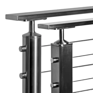
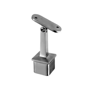
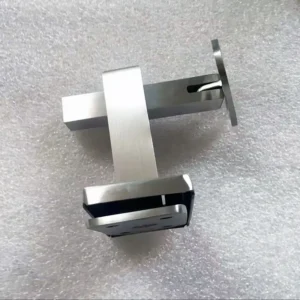
Handrail splice and support locations are set by the installed assembly first and the shipping plan second: fix the bracket or post positions, the corners, landings, changes in pitch, the run ends and the points where a worker can actually get a tool to the joint, then place the breaks where a splice can be assembled and where the connection designer accepts it. Stock tube length matters, but it is one input among several, not the starting point. A splice here means any joint in the continuous handrail tube, whether it is an internal sleeve that only lines the two ends up or a connection designed to transfer forces between the rail lengths it joins.
Two conditions change that answer materially. If the run crosses a building movement joint or has a stated movement requirement, the joint arrangement at that location is a design decision, not a fabrication convenience. And if the project specifies a named engineered handrail system, the manufacturer’s own system documentation may already limit where splices are permitted, which overrides a layout you would otherwise draw freely.
Lay out supports and transitions before shipping breaks
Draw the fixed geometry of the run before you draw a single break. That means every wall bracket or post location, every corner and change of direction, every landing, both ends of the run with their extensions, and the positions where an installer can physically reach in with a hex key or a drill to close a joint. Only once that layout exists does shipping length become useful, because it tells you how many breaks you need, not where they belong.
The reason for that order is simple. A splice location has to satisfy two different plans at once: the transport and handling plan that gets the material to site in manageable modules, and the installed assembly that has to be aligned, fixed and loaded. A break placed purely to suit a stock length can land in a position where the joint cannot be reached, cannot be pulled tight, or sits where the rail changes direction. Reversing the order avoids rework at the only stage where rework is expensive.
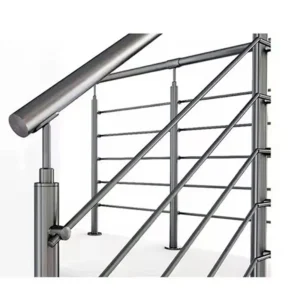
Access deserves its own pass over the drawing. On a wall-mounted run, a splice tight against a wall or behind an obstruction can leave no room to drive a set screw or to slide a sleeve the distance it needs to travel during assembly. On a post-mounted run, the same joint may be clear on the drawing but blocked by the post, an infill panel or a top-rail transition once the assembly is built up. Walk the sequence mentally in the order the installer will build it, not in the order the parts appear on the cut list.
Where the project names an engineered system, check its documentation before committing. Some systems constrain permissible splice positions relative to supports as part of how the system was designed and assessed, and those constraints come from the system manufacturer rather than from your layout logic.
Confirm the structural function of each splice
Every splice between supports needs a stated function, confirmed with the connection designer, before it is drawn. The functional question is whether the joint only keeps two tube ends concentric and visually aligned, or whether it is intended to transfer forces between the rail lengths it joins. Those are different details with different hardware, different fastening and different consequences for how the supported lengths behave.
The difficulty is that both details can look identical once installed. An alignment sleeve and a force-transferring connection both disappear inside the tube and both leave a clean exterior line. A concealed joint tells you about the appearance of the finished rail; it tells you nothing about what the joint carries. What decides capacity is the connection design itself, as defined by the party responsible for it, so do not infer joint capacity from how the completed rail looks.
This matters most for the segments either side of the break. If the joint is an alignment sleeve only, the rail lengths it separates behave as separate supported members, and the unsupported span on each side is measured to the supports, not to the sleeve. If the joint is designed to transfer assembly forces, the lengths interact and the span logic changes. Guard and handrail loads, and the deflection permitted under them, are the connection designer’s determination for the project; ASTM E985-24 is the standard covering permanent metal railing systems, stair rails, ramp rails and handrails for buildings, including basic design and load and deflection criteria, while the specific criteria applied to a given run remain project responsibilities and the standard excludes ballasted systems and workplace occupancies governed by occupational-safety requirements.
The practical output of this step is a note against each splice on the drawing saying which function it performs. That single annotation prevents a shop from substituting a simpler internal sleeve where a designed connection was intended.
Check joint and bracket interference near supports
A splice placed at or near a support has to pass a physical fit check covering four things at once: the bracket or post fitting, the sleeve or connector body, the fasteners that close the joint, and any movement the assembly needs during installation. If all four cannot occupy the same region of tube and still be reached, the location fails regardless of how good it looks structurally.
The pull toward supports is understandable. Moving a joint closer to a bracket shortens the unsupported segment on one side and can make the span arithmetic easier. But the same move concentrates hardware. The bracket’s saddle or its fixing screws can sit exactly where the connector’s set screws need to land. A sleeve that must slide a given distance into one tube before the second tube is offered up may have no room to make that travel if a bracket is already fixed in the way. The joint becomes undrawable in the field even though it is drawable on paper.
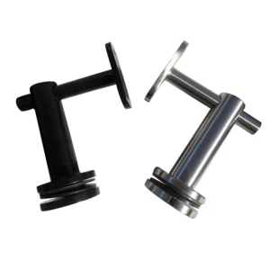
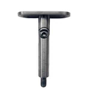
Accessibility after assembly is the other half of the check. Set screws, pins or through-fixings should remain reachable for the tightening sequence the connector requires, and a wall or post immediately behind the joint can take that away. On wall-mounted rails the bracket projection governs how much working space sits between the tube and the wall; on post-mounted rails the post cap or top-rail fitting governs clearance at the same point.
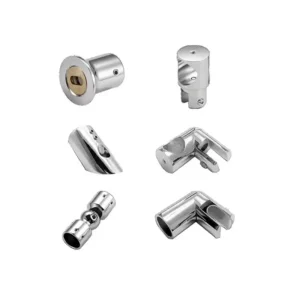
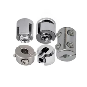
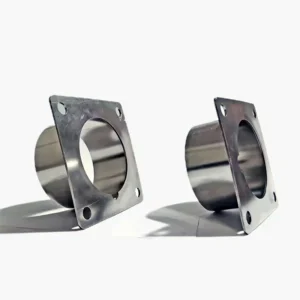
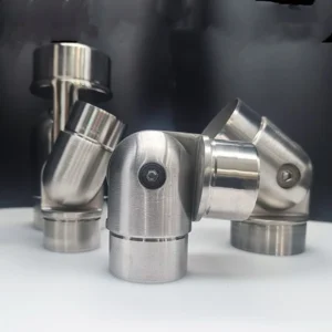
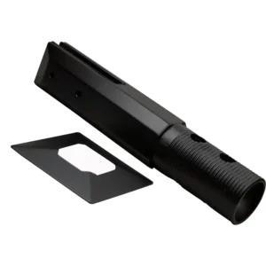
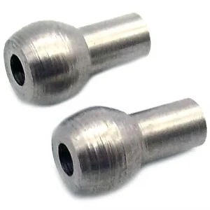
Where a splice genuinely must coincide with a support, the resolution is a documented combined detail from the supplier or the connection designer that shows the bracket and the joint working together, with the fastener positions and the assembly sequence shown. Within ESANG’s rail connector families, the governing dimensions are the connector body length, the fastener positions along it and the insertion travel the joint requires; those three numbers, checked against the bracket footprint, decide whether a near-support splice is buildable.
Resolve continuity and movement at changing geometry
| Condition d'exécution | What to coordinate with the splice location | Question to resolve |
|---|---|---|
| Corner, landing or change in pitch | Required rail continuity and the actual fabrication geometry at the transition | Does the connection work at this change in geometry, rather than simply repeat the straight-run spacing pattern? |
| Building movement joint or significant movement requirement | The rail’s movement arrangement and support layout | What required movement and joint behavior has the responsible designer defined? |
Transitions and movement locations are the two places where a straight-run spacing pattern fails, and they fail for different reasons. At a corner, landing or change in pitch, the problem is geometry: the rail has to remain continuous and graspable through the change, while the fabricated bend or transition fitting occupies tube length that a repeating pattern did not allow for. At a building movement joint, the problem is behavior: the rail has to accommodate relative movement that an ordinary fabrication splice was never designed to provide.
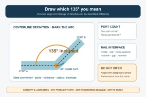
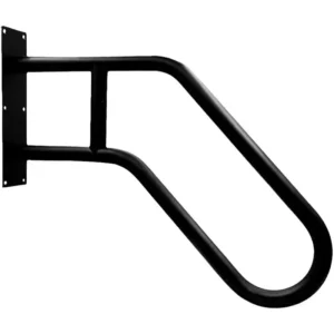
Take the transition case first. If you lay out splices by stepping a fixed dimension along the run, the pattern eventually lands a break at or immediately beside the point where the rail turns or changes pitch. That is the hardest place to make a connection, because the two tube ends are no longer collinear, the connector body may not fit through the bend, and the joint sits where the user’s hand is most likely to travel. Coordinate joint positions against the actual fabrication geometry at each transition, including how the bend or transition fitting is made, rather than against a nominal spacing. Where the stair or ramp is a covered means of egress, the Access Board’s guide to stairways addresses handrail continuity, gripping surfaces, clearance and extensions, and those criteria apply within U.S. accessibility and covered-facility scope, so confirm which requirements the project has adopted before fixing dimensions at a transition.
Movement is a separate determination. A splice added for fabrication or transport convenience has no documented movement function: it may be a tight sleeve, a fixed connection or a joint with incidental clearance, and none of those is a movement detail. Where the run crosses a building movement joint or the project states a movement requirement, the responsible designer defines the movement to be accommodated and the behavior the joint must provide, and that arrangement is then resolved together with the support layout so the rail is held where it needs to be held and free where it needs to be free. Adding an arbitrary loose splice at the movement joint substitutes a guess for that definition.
Issue a location-based splice and support drawing
Issue a keyed run drawing, not a spacing rule, when the layout goes to the supplier. The drawing should carry a unique mark at every support and every splice along the run, and for each mark it should state the splice type, the joint’s orientation and rotation, the field access available at that point, and which transport module the adjacent rail length belongs to. Mark a landing splice separately from a stair-flight splice even if the connector part number is the same, because the questions each one raises are different.
Keying each location this way lets constructability and structural questions be answered where they actually arise. A reviewer can look at mark 7 and ask whether the sleeve clears the bracket at that bracket, rather than asking a general question about splices near supports that has no single answer. It also makes the division of responsibility visible: which joints the connection designer has defined, which are alignment only, and which are still open.
A generic statement of support spacing or splice spacing is not a substitute for this drawing. Spacing rules describe a pattern; the project design has to resolve specific supports, specific substrates and specific transitions, and a pattern cannot carry the exceptions created by corners, landings, movement joints and access restrictions. Where the drawing feeds a submittal package, the keyed splice layout and the statement of who has designed which connection belong in it alongside the rest of the handrail documentation.
To get a useful first response from a supplier, have the keyed run drawing with support and splice marks, the substrate and fixing conditions at each support, the stair and ramp geometry at every transition, any stated movement requirement and its location, the specified stainless-steel grade and finish, and the exposure the installation faces. With those in hand, connector families and joint details can be matched to locations rather than discussed in the abstract, and any decision to accept a particular splice arrangement stays with the project’s approved procedure and its designated approver.
Questions fréquemment posées
Q : Is a concealed sleeve enough to approve a splice between supports?
A : Its appearance is not enough. Confirm whether the proposed joint only aligns the rail or is intended to transfer forces, and have that function checked against the supported rail lengths at its actual location. Do not treat all internal sleeves as interchangeable connections.
Q : What should I do if the shipping breaks leave a joint difficult to assemble on site?
A : Reconsider the break location or use a documented compatible connection detail before finalizing the transport modules. Check the sleeve, bracket, fasteners, required assembly movement and access together; a convenient shipping length does not establish that the installed joint can be assembled.
Q : Can the same splice detail be used on both a stair flight and a landing?
A : Only where it works with the geometry and required rail continuity at each location. Identify the flight and landing joints separately on the drawing, including their orientations, rather than assuming that a repeated straight-run detail will suit both.
Q : How can I compare supplier proposals that place splices in different locations?
A : Compare them against the same keyed run drawing showing supports, transitions, ends and field access. For each proposed splice, identify its intended function and check how it fits the surrounding hardware and assembly sequence. Compare the installed arrangements as well as the transport lengths.