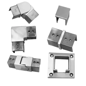
Specifying handrail tube internal sleeves and splice locks starts with the inside of the tube, not the outside. A concealed connector seats against the bore, so the governing figures are the tube’s actual inside dimensions at the ends being joined — section, wall thickness and the tolerance on both — plus whether the joint only needs the two ends brought into line or needs a connection that positively resists separation and rotation. An internal sleeve is a sized insert that spans the joint inside the tube; a splice lock is a connector with a mechanical feature, reached through the tube or a cover, that retains the two ends once they are seated.
Those two decisions — the internal envelope, and the function the joint has to perform — settle most of the specification. What remains is whether the installer can physically insert the connector and reach the locking feature in the sequence the rail will actually be assembled.
Match the sleeve to the tube interior
Request a concealed connector against the tube section, wall thickness and dimensional tolerance, not the outside diameter alone. Two tubes can share an identical outer profile and finish and still present different internal envelopes, because wall thickness and mill tolerance vary between suppliers, production runs and standards. Organización Internacional de Normalización describes diameters, dimensional tolerances and conventional masses for stainless steel tubes, which is useful for understanding how much variation a nominal size may legitimately carry; it governs the tube’s dimensions and says nothing about engagement, retention or railing performance, which depend on the joint you build. The exception is a matched system drawing that already defines and controls both the tube and the connector — there the fit is designed and the dimensions are fixed by the system supplier.
Having the dimensions on paper is the first step, not the whole check. Welded tube carries an internal seam, and depending on how it was produced that seam may stand proud enough to obstruct a close-fitting sleeve even when the nominal bore is correct. A splice that crosses a change in tube profile — a different wall, a different radius on a shaped section, a transition from one run to another — introduces the same risk from a different cause.
So trial-fit the proposed sleeve or splice lock with the actual mating ends before the order is placed. Check three things in sequence: that the connector enters, that it seats to the intended depth on both sides, and whether any particular orientation is needed to clear the seam or an internal feature. If orientation matters, that orientation belongs on the joint detail, because the installer will not see the seam once the tube ends are together.
A dimensional match on paper can miss an obstruction sitting directly in the path of insertion, and the discovery usually comes on site with the rail already fixed at one end. For the same reason, confirm the internal envelope at the specific ends to be joined rather than at a convenient offcut, since tube tolerance is a band, not a single number.
Choose between alignment and positive retention
| Joint function | Datos que hay que confirmar | What to verify |
|---|---|---|
| Bring mating tube ends into line | Alignment sleeve and seating at both ends | Outside faces meet as intended on the trial assembly |
| Resist separation or rotation | Positive retention in the documented connector detail | What retains each end and how the installer can reach it |
| Transfer force along the run | Connection reviewed with the actual support layout | Which parts and supports are relied on for the intended load transfer |
Seating two tube ends concentrically and holding them together in service are different tasks, and a connector offered for one does not automatically perform the other. An alignment sleeve centers the mating ends so the outside faces of the tube meet cleanly and the joint reads as a continuous run. A splice lock adds a mechanical feature — the detail varies by connector — that resists the ends pulling apart or rotating relative to each other once assembled.
Ask any supplier offering a concealed connector what prevents separation and what prevents rotation, treating those as two separate answers, and then specify the detail that matches the joint’s intended function. A sleeve can carry retention where the documented system detail assigns it that role, but that role has to be documented rather than assumed from the fact that the fit is tight.
Where the splice is intended to transfer force along a supported rail run, the connection and the support arrangement work together, and neither can be judged from the connector alone. Show the joint next to its actual supports on the drawing — bracket or post positions either side, spans, and where the joint falls within the span — and have the connection reviewed for that role before any substitution is accepted. A trial fit that feels solid in the shop tells you the parts assemble; the service role of the joint depends on what retains the connection and how the run is supported around it.
That review belongs with the party responsible for the railing design. ASTM E985-24 covers permanent metal railing systems and rails for buildings, and its public scope identifies basic design and load or deflection considerations for those systems; it excludes workplace occupancies subject to occupational-safety requirements, and in any case the connection criteria for a particular joint stay project-specific. Acceptance of a proposed splice detail for a load-transferring position is a decision for the project’s approved procedure and its designated approver, not something the connector catalog settles.
Check insertion and tool access before locking the run
A connector that fits the bore can still be impossible to seat or lock in the sequence the rail is actually assembled, so test the specification against the assembly order on the drawing. The constraint is simple: an internal connector has to slide into one tube before the second tube closes over it, which means at least one of the two tubes must be free to move along the rail axis by roughly the engagement depth of that side.
This bites hardest on a short section closed between supports that are already fixed — a landing infill between two posts, or a return that is welded or bracketed at both ends. Once both ends are captive, neither tube can travel, and the connector has nowhere to enter. For those joints the drawing should state which tube slides during assembly, how far the connector enters on each side, and where the installer reaches the locking feature.
That last point is what turns a splice lock from a catalog item into a buildable detail. If the lock is driven through a hole in the tube wall, the hole position has to be reachable with a tool at the installed height and orientation, clear of a wall, a glass panel, a post or a bracket. If it is reached from an open tube end, that end has to still be open at the moment of locking, which fixes the order of operations for the whole run.
The alternative is to change the sequence rather than the connector: an accepted assembly sequence can close the splice first, on the ground or on the bench, and fix the supporting posts or brackets afterward. That trade is worth making explicit on the drawing, because it moves the critical tolerance from the connector to the support positions, and the installer needs to know which one is governing before the first anchor goes in.
Direction of assembly and available access interact, and neither is visible in a connector part number. Decide both at the drawing stage and the installer inherits a joint that can be built in the order the site allows.
Write a connector schedule the shop can build from
A connector schedule is a list of joints, not a list of parts, with one line per joint carrying everything needed to buy the connector and build the joint. A workable line reads something like: landing straight splice — tube section and wall, connector internal dimension, engagement at both ends, retention method, assembly direction, access point for locking. The joint reference at the front is what keeps a concealed part traceable to the specific position it belongs in, which matters because once the rail is assembled nobody can see which connector went where.
The schedule earns its keep on orders covering several joints that look identical in elevation. Two straight splices in the same run can differ in the tube wall they join, in whether one side has to slide, or in whether a nearby post blocks the tool path to the locking feature. Group repeated joints under one detail only when both ends and the installation access genuinely match; if either differs, give the joint its own line even though the connector part may turn out to be the same.
Retention method and assembly direction are the two fields most often left blank, and both are decisions rather than descriptions. Retention method states what holds the joint together — alignment only, or a named positive feature — and assembly direction states which tube moves and from which side the connector enters. Filling them forces the question of whether the joint has been thought through at all, long before a connector is cut.
For the supplier discussion, have the tube section and wall thickness with their tolerance, the mounting drawing showing each splice with the posts or brackets either side, the engagement you expect at each end, the specified stainless grade and finish, and a note of the exposure if the run is outdoors or coastal. With those in hand a connector can be matched to the joint rather than to the elevation, and any trial fit you run afterward confirms a decision instead of substituting for one.
Preguntas frecuentes
P: Can I reuse the same connector when the next shipment has the same tube part number?
A: Keep it on the schedule only if the replacement tube is controlled to the same mating requirements. If the supplier or tube specification changes, repeat the fit check on representative ends before committing the batch.
P: What should I ask for if a proposed substitute hides its locking feature?
A: Ask for a section through the assembled splice and an explanation of how the installer can verify retention after seating it. If it cannot be checked after closure, agree what to record while the feature is still visible.
P: Is a fit sample from the supplier enough when the last rail segment is trapped between two returns?
A: Use the sample for component fit and check the closing sequence on the actual layout as a separate step. Show which parts will already be fixed when the final segment is offered up.