Los planos arquitectónicos de las esquinas de las barandillas de cable suelen mostrar el aspecto que tiene un poste terminado sin especificar cómo termina en él cada cable. Esa brecha entre la apariencia y la intención estructural es donde se acumulan los trabajos de corrección en los proyectos: postes encargados con un patrón de orificios incorrecto, cables tendidos alrededor de una esquina sin el accesorio adecuado y problemas de tensión descubiertos durante la instalación que obligan a retirar los herrajes ya fijados al armazón de la terraza. Las decisiones que evitan esos problemas —tipo de poste, orientación de la barandilla, método de tendido del cable, herrajes por tramo— se toman todas antes de los planos de taller, lo que significa que deben tomarse antes de que comience la fabricación, y no resolverse sobre el terreno. A continuación se presenta un marco para identificar cuáles de esas decisiones siguen pendientes en su proyecto y cuánto cuesta cada una de ellas si se aplaza.
Direcciones de las fuerzas en las esquinas de las barandillas de cable
Un poste de esquina no es un poste intermedio estándar sometido a una única dirección de carga. Cuando se cruzan dos tramos de cable, el poste soporta la tensión de ambos simultáneamente, y esas tensiones no se anulan, sino que se suman. Dependiendo del ángulo entre los tramos y de la tensión del cable especificada, la fuerza resultante puede ser considerablemente mayor que la que ejercería cada tramo por separado, y actúa en una dirección que varía en función de la geometría de la esquina.
La consecuencia práctica es más evidente en la construcción de terrazas de madera. Tender el cable alrededor de un único poste de madera sin los herrajes de esquina adecuados genera una presión lateral concentrada que, con el tiempo, puede desviar el poste de su alineación vertical o arrancarlo de su unión con el armazón de la terraza. No se trata de un modo de fallo teórico, sino de un resultado documentado de tratar un poste de esquina como si funcionara como un poste pasante. El fallo se desarrolla gradualmente, lo que significa que el poste puede parecer estable durante la inspección y solo mostrar un desplazamiento tras repetidos ciclos de carga estacionales.
Una solución de diseño al problema de la carga combinada es una configuración de esquina con dos postes, en la que cada poste tiene su propio punto de anclaje independiente y soporta la tensión de un solo tramo de cable. Al distribuir la carga entre dos uniones estructurales independientes, este enfoque evita que la resultante combinada se concentre en la base de un único poste. Se trata de una estrategia específica de cada fabricante, más que de un requisito universal de la normativa, pero refleja una lógica estructural sólida: separar los puntos de anclaje reduce la fuerza neta a la que debe resistir cada poste individual y proporciona a la subestructura una base más amplia sobre la que distribuir dicha carga.
La norma ASCE/SEI 7-22 establece las combinaciones de cargas que rigen el diseño de los sistemas de barandillas, y el ingeniero estructural responsable debe evaluar cualquier configuración en una esquina de cables según dichos criterios. La cuestión aquí es más concreta: si tu plano arquitectónico muestra un único poste de esquina sin definir cómo se resuelve estructuralmente la tensión combinada de los cables, la transmisión de cargas queda sin resolver. Se trata de una decisión de diseño, no de una preferencia de detallado.
Soluciones de fijación que evitan la abrasión y la rotación
Pasar el cable por el interior o por el exterior de un poste de esquina sin el accesorio adecuado da lugar a dos mecanismos de fallo distintos, y ninguno de ellos se corrige por sí solo.
El primero es la abrasión. Cuando el cable entra en contacto con un orificio de poste sin revestimiento y sin un elemento aislante, cada ajuste y cada ciclo de carga genera fricción contra los hilos exteriores del cable. En los postes metálicos —especialmente los de aluminio—, este contacto también supone un riesgo galvánico: un cable de acero inoxidable en contacto directo con el aluminio crea una situación de metales diferentes que provoca corrosión electrolítica. El cable puede parecer intacto en la superficie, mientras que los hilos individuales se están degradando en el punto de contacto dentro del orificio. Los ojales de plástico son una solución especificada por el fabricante para este problema, ya que aíslan el cable de la pared del orificio e interrumpen el contacto metal con metal. Se trata de un detalle preventivo práctico para los postes metálicos, no de un requisito normativo universal, pero cuando la combinación de materiales genera un riesgo galvánico, la decisión de no utilizar un elemento aislante supone un fallo de compatibilidad de materiales que acabará manifestándose a lo largo de la vida útil de la instalación.
El segundo mecanismo de fallo es la rotación del poste. Un cable que no esté correctamente rematado en una esquina puede ejercer un par neto sobre el poste al aplicar o ajustar la tensión. Si la conexión de la base del poste no resiste por completo ese par —o si el cable hace presión contra la pared del orificio en ángulo—, puede producirse una rotación gradual. A diferencia de un fallo repentino, este es progresivo y puede pasar desapercibido hasta que el poste se desalinee visiblemente o el orificio se alargue lo suficiente como para que los herrajes de los extremos ya no encajen correctamente.
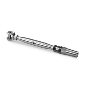
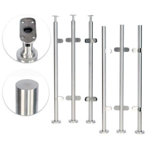
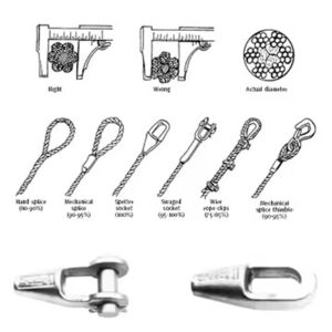
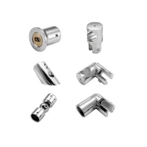
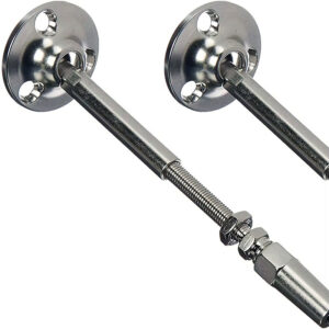
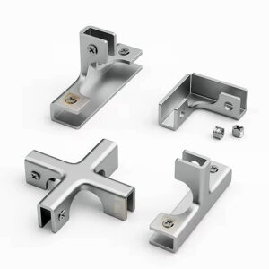
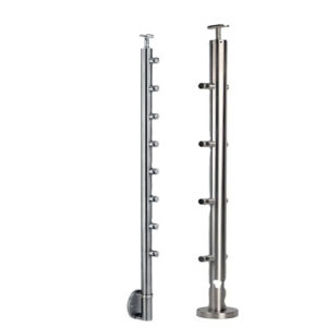
La elección de los herrajes en las esquinas —ya sea un accesorio de terminación adecuado, un ojal o una configuración de paso con la geometría correcta— es lo que determina si se gestionan estos riesgos. En el caso de los postes metálicos huecos en los que no se puede instalar un terminal roscado estándar o un paso, existen alternativas como las palancas de bloqueo o los terminales de pasador que ofrecen una vía de terminación válida, pero esas opciones deben identificarse antes de fabricar el poste, y no improvisarse in situ. La solución de herrajes específica determina el tamaño y la posición de los orificios; una vez taladrado el poste, esos parámetros no pueden modificarse.
Secuencias continuas frente a terminaciones independientes
La elección entre tender el cable de forma continua a través de un poste de esquina y terminar cada tramo de forma independiente supone una verdadera disyuntiva de planificación con consecuencias para el tensado, el número de accesorios y el mantenimiento futuro; no se trata de una decisión relacionada con el cumplimiento de la normativa.
En una configuración continua, el cable pasa por el poste de esquina sin terminación, lo que reduce el número total de terminales de tensión del sistema. La limitación es que el ajuste de la tensión en cualquier parte de ese tramo afecta a todo el tramo del cable. En una esquina en la que dos tramos comparten una línea continua, volver a tensar un lado puede desplazar la tensión del otro, y la futura sustitución del cable requiere volver a tender un tramo más largo en lugar de aislar un solo tramo.
La terminación independiente hace que cada tramo de cable termine en el poste de esquina y que el tramo adyacente comience por separado. Esto supone un mayor número de accesorios —kits de tensión y kits de montaje en el interior del poste independientes para cada línea en cada esquina—, pero permite tensar cada tramo de forma aislada. Además, limita el alcance de cualquier sustitución futura a un único tramo sin afectar a los tramos vecinos. La incorporación de un segundo poste en la esquina hace que este enfoque sea sencillo desde el punto de vista estructural, ya que cada tramo termina en su propio poste en lugar de compartir una conexión estructural.
| Acérquese a | Requisitos de hardware | Control de la tensión | Repercusiones de la sustitución |
|---|---|---|---|
| Continuo (de paso) | El cable pasa por el poste de esquina sin terminación; hay menos terminales de tensión en total | La tensión se distribuye a lo largo de todo el tramo del cable; el ajuste afecta a varios tramos al mismo tiempo | La sustitución de un solo cable puede requerir volver a tender un tramo más largo y afectar a los tramos adyacentes. |
| Independiente (cerrar y reiniciar) | Cada tramo de cable termina en el poste de esquina mediante kits de tensión independientes y kits de montaje en el interior del poste. | Cada tramo cuenta con un ajuste de tensión independiente que permite un control preciso y aislado. | La sustitución se limita a un tramo; los tramos adyacentes no se ven afectados. |
La tabla anterior recoge la comparación estructural, pero la decisión tiene una consecuencia posterior menos evidente: la elección determina qué patrón de orificios para postes necesitas. Un poste configurado para una terminación independiente debe poder alojar dos accesorios de terminación en la intersección de las esquinas. Un poste configurado para un paso continuo necesita una geometría de un solo orificio alineado con el recorrido del cable. Pedir el tipo de poste equivocado —incluso con el diámetro y el acabado correctos— puede hacer que resulte inutilizable sin tener que volver a taladrarlo, lo cual, en el caso de los postes de acero inoxidable fabricados, no es una corrección que se pueda realizar in situ. Esta es la razón por la que la decisión sobre el trazado debe preceder a la lista de herrajes, que a su vez debe preceder a los planos de taller.
Información que falta en los detalles arquitectónicos de las esquinas
Los detalles arquitectónicos de las esquinas de las barandillas de cable suelen mostrar el perfil visible del poste, su acabado y su geometría aproximada, sin especificar la información necesaria para su fabricación. La representación estética y las especificaciones estructurales son dos documentos distintos y, en muchos detalles de esquinas, solo existe el primero.
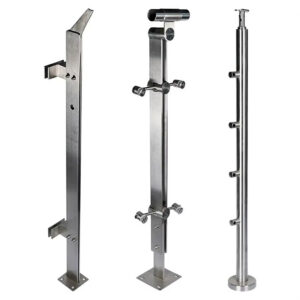
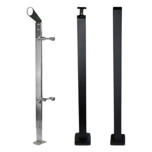
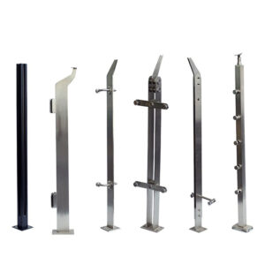
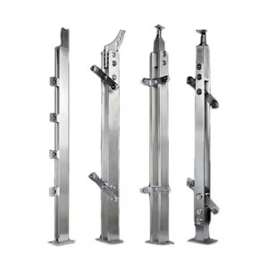
Cuando no se especifica el tipo de configuración del poste —ya sea una esquina entre dos niveles, una transición de escalera a nivel o una transición de escalera a nivel con cambio de altura—, no es posible determinar la disposición de los orificios necesaria para esa geometría. Las diferentes configuraciones requieren tamaños y posiciones de orificios distintos para cada tramo que se cruza; un poste fabricado para una esquina entre dos niveles no se adapta a un tramo de cable en ángulo sin modificaciones. Cuando no se especifica la orientación de la mano, un poste taladrado para una esquina a la izquierda no puede utilizarse en una esquina a la derecha, y esa distinción se establece en el momento de la fabricación. Cuando falta el ángulo de la escalera en el detalle de una esquina en ángulo, no es posible encargar postes en ángulo con la geometría correcta, y los kits de tensión que sirven para el tramo en ángulo dependen de esa misma medida.
Cada uno de estos detalles que faltan tiene una consecuencia directa en el orden, en lugar de dar lugar a una vía de corrección de campo.
| Dato que falta | Por qué es importante | Qué confirmar |
|---|---|---|
| Tipo de configuración del poste (C, D o I) | Cada tipo (esquina a nivel, paso de escalera a nivel, transición de escalera con cambio de altura) requiere una disposición de orificios y unos herrajes de sujeción diferentes. | Comprueba qué tipo de poste se ajusta a la geometría real de la esquina |
| Tamaño y disposición de los agujeros | Las dimensiones de los orificios (por ejemplo, 1/2″ frente a 5/16″) determinan qué kits de tensión y qué accesorios son compatibles. | Consigue las especificaciones del patrón de orificios para cada tramo que se cruce, a fin de evitar incompatibilidades en los herrajes. |
| Método de terminación de cables por tramo | El paso continuo y la terminación independiente requieren diferentes preparaciones de los postes y un número distinto de elementos de fijación. | Indica si cada línea de cable pasa por el poste de esquina o termina en él. |
| Orientación de la mano (izquierda/derecha) | Los postes C e I requieren seleccionar si son para la izquierda o para la derecha; una elección incorrecta provoca que los orificios queden desalineados | Comprueba que la orientación de cada poste de esquina sea la correcta |
| Ángulo de la escalera | Los postes en ángulo (D e I) se fabrican con un ángulo específico y requieren kits de tensión angular a juego. | Indique el ángulo exacto de la escalera al realizar el pedido |
La tabla ofrece una lista de comprobación estructurada, pero conviene mencionar explícitamente la cadena de causa y efecto. La falta de una designación del tipo de poste da lugar a una disposición incorrecta de los orificios. Una disposición incorrecta de los orificios implica que los accesorios de terminación no se pueden instalar según lo especificado. Los accesorios que no encajan correctamente no se pueden tensar según las especificaciones, y un sistema de cables que no se pueda tensar adecuadamente no cumplirá los requisitos de carga que se espera que satisfaga la instalación según la norma ASTM E935-21. El camino desde la ausencia de un detalle de la especificación hasta un resultado de rendimiento deficiente es corto, y ninguno de los pasos intermedios es recuperable sin fabricar el poste correcto.
Las convenciones de nomenclatura utilizadas por cada fabricante —ya sea la taxonomía C/D/I u otro sistema— no deben interpretarse como una norma válida para todo el sector. Lo que representan es el grado de especificidad que requiere cada detalle de las esquinas. Independientemente de la notación que utilice su proyecto, cada poste de esquina necesita una geometría definida, una disposición de orificios definida, una orientación de la manilla definida (si procede) y un juego de herrajes definido antes de poder encargarse.
Decisión sobre los planos de taller para cada tramo que se cruza
Los planos de taller no pueden absorber sin coste alguno las decisiones sobre detalles que se han pospuesto. Cuando el tipo de poste, la orientación de la barandilla, el ángulo de la escalera y la asignación de herrajes por tramo quedan sin resolver en la fase de los planos de taller, las consecuencias en el calendario se agravan rápidamente: los planos de taller se emiten con marcadores de posición o detalles incorrectos, la fabricación se lleva a cabo basándose en suposiciones y el conflicto sale a la luz durante la instalación, cuando los plazos de refabricación ya no pueden recuperarse dentro del calendario de obra.
La cuestión de la asignación de los herrajes es especialmente importante en las esquinas, donde los tramos de cable horizontales y en ángulo se cruzan en el mismo poste. En esa configuración, el poste requiere orificios de diferentes tamaños para cada tramo y diferentes kits de tensión que se adapten a cada recorrido del cable. El plano de taller debe especificar qué kit corresponde a cada tramo. Si no lo hace —es decir, si el plano muestra la geometría del poste sin asignar los herrajes a cada tramo que se cruza—, la lista de materiales no se podrá elaborar con precisión y existe un riesgo significativo de recibir el poste correcto con un juego de herrajes incompleto o inadecuado.
| Punto de decisión | Aplicable a | Por qué es necesario especificarlo |
|---|---|---|
| Tipo de puesto (C, D o I) | Todos los postes de esquina | Determina la disposición correcta de los orificios, el juego de herrajes y el método de fabricación |
| Orientación de la mano (izquierda/derecha) | Entradas de C e I | Es imprescindible para taladrar con precisión y alinear los herrajes; no se puede modificar una vez fabricado. |
| Ángulo de la escalera | Entradas de D y yo | Los postes en ángulo se construyen con un ángulo específico; los kits de tensión angular dependen de la medida correcta |
| Asignación de herrajes por tramo de intersección (kit de tensión horizontal frente a kit de tensión angular) | Posición D (utiliza ambas) | El poste D combina tramos horizontales y en ángulo; los planos de taller deben indicar qué tramo corresponde a cada kit para evitar errores en los pedidos |
| Enrutamiento continuo frente a enrutamiento independiente para cada línea de cable | Todos los postes de esquina | Define el número de terminales, los orificios pasantes y la lista de materiales para todo el conjunto de la esquina |
Las entradas relativas a la orientación de la escalera y al ángulo de la misma en la tabla de decisiones no son detalles que puedan corregirse tras la fabricación. Un poste taladrado para una orientación a la izquierda no puede reutilizarse en una esquina a la derecha. Un poste en ángulo fabricado con un ángulo de escalera incorrecto requiere que se indique el ángulo de la escalera en el momento de realizar el pedido, lo que significa que el ángulo estructural debe confirmarse a partir de los planos de construcción reales o mediante una verificación in situ antes de incluir esa partida en el pedido. No se trata de preferencias de diseño con flexibilidad de instalación, sino de parámetros fijos desde el momento de la fabricación.
En el caso de condiciones atípicas —postes metálicos huecos en los que no sea posible utilizar terminales roscados o de paso—, existen alternativas de terminación, como los cierres de palanca y los terminales de pasador. Se trata de opciones de contingencia para configuraciones específicas de postes, no de elementos que deban figurar en todos los planos de obra. Su pertinencia debe evaluarse poste por poste, en función de lo que requieran el tipo de poste y su estado estructural. Para obtener más información sobre cómo la configuración de los postes interactúa con los requisitos de tensión en todo un sistema completo de barandillas de cable, Sistemas de postes de barandilla de cable de acero inoxidable: Especificaciones de diseño y requisitos de tensado para cubiertas residenciales y comerciales abarca la lógica de selección en su conjunto.
La aprobación de los planos de taller es el último momento en el que las decisiones relativas a los herrajes de las esquinas pueden modificarse sin que ello suponga un coste elevado. Una vez iniciada la fabricación, cada corrección conlleva un plazo de entrega, un coste de refabricación y un retraso en el calendario; ninguno de estos aspectos queda cubierto por la revisión de los planos. Las decisiones descritas en la tabla anterior no son detalles que deban confirmarse durante la instalación, sino requisitos que debe cumplir un conjunto de planos de taller correcto.
Lo que hace que las decisiones relativas a los herrajes de los postes de esquina sean tan importantes es que abarcan tres fases distintas —planificación estructural, detallado arquitectónico y fabricación— y los errores cometidos en cualquiera de ellas no se hacen evidentes hasta la siguiente. La discrepancia entre lo que muestra un plano arquitectónico y lo que requiere la fabricación es el origen de la mayoría de los problemas en las esquinas: un poste representado correctamente en el alzado, pero al que le faltan los datos de configuración necesarios para encargarlo y fabricarlo con precisión.
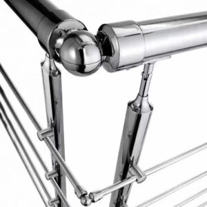
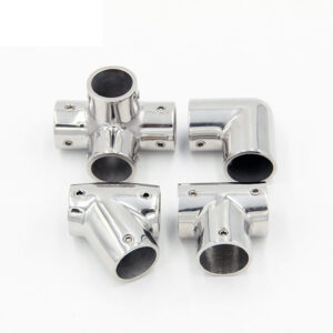
Antes de emitir los planos de ejecución, comprueba que cada poste de esquina tenga un tipo definido que se ajuste a su geometría real, un método de tendido especificado para cada tramo de cable que se cruce y una asignación completa de los accesorios. Cuando se trate de tramos en ángulo, el ángulo de la escalera debe verificarse a partir de los documentos de construcción, en lugar de darlo por supuesto. El herrajes para cables de esquinero Las opciones disponibles para una configuración determinada de poste se reducirán considerablemente una vez que se hayan fijado el trazado y el método de terminación, momento en el que será posible elaborar una lista de materiales clara y un plano de taller preciso.
Preguntas frecuentes
P: En mi proyecto utilizo postes de acero con placas de base soldadas en lugar de una plataforma de madera. ¿Sigue siendo válida la lógica que sustenta el uso de dos postes en las esquinas?
R: Sí. La carga de tracción combinada actúa sobre la base del poste independientemente del material, por lo que separar los puntos de anclaje sigue distribuyendo la tensión sobre una superficie más amplia de la subestructura y reduce el riesgo de rotación del poste o de sobrecarga en la unión. El modo de fallo cambia —las placas de base soldadas son menos propensas a desprenderse, pero aún así pueden ceder o transmitir un momento excesivo—, por lo que el razonamiento sobre la trayectoria de la carga sigue siendo relevante incluso cuando la estructura del tablero no contiene madera.
P: Una vez que haya decidido si voy a optar por un trazado continuo o independiente para cada esquina, ¿cuál es el siguiente paso más eficaz antes de ponerme en contacto con un proveedor?
R: Elabora una lista de herrajes para esquinas en la que se especifiquen el tipo de poste, la orientación del pasamanos, el ángulo de la escalera (si procede), el método de tendido de los cables y el kit de herrajes específico para cada tramo que se cruza en cada esquina del proyecto. Este único documento convierte tus decisiones sobre el trazado en una solicitud de lista de materiales que el proveedor puede presupuestar sin necesidad de aclaraciones repetidas, y elimina el riesgo de que en la fase de planos de taller se mantengan datos sin resolver sobre las esquinas.
P: ¿A partir de qué ángulo de curvatura la fuerza ejercida por el cable resulta excesiva para un solo poste con los accesorios adecuados?
R: No existe un umbral universal fijo, pero la fuerza resultante aumenta considerablemente a medida que se reduce el ángulo interior. En las esquinas interiores con un ángulo inferior a unos 45 grados, la componente lateral suele ser tan intensa que una configuración de un solo montante conlleva el riesgo de que este se deforme o de que se produzca una sobrecarga en los herrajes, incluso con los accesorios adecuados. En esos casos, lo más prudente es optar por una esquina de dos montantes o por un detalle de ingeniería a medida evaluado según las trayectorias de carga de la norma ASCE/SEI 7-22.
P: ¿Cómo debería sopesar el ahorro inicial en hardware que supone un tendido continuo en esquina frente a la ventaja que ofrecen las terminaciones independientes en cuanto a facilidad de mantenimiento?
R: Las instalaciones continuas reducen el número de terminaciones y el coste de los materiales en la actualidad, pero transmiten la tensión a lo largo de los tramos y hacen que la futura sustitución de los cables sea un trabajo de mayor envergadura; las terminaciones independientes suponen un gasto adicional en material y más tiempo de instalación, pero permiten que el tensado y la sustitución se limiten a un único tramo. En proyectos en los que el tiempo de inactividad o la mano de obra necesaria para volver a tensar el cable resultan costosos —como en balcones comerciales o terrazas públicas—, el enfoque independiente suele resultar rentable al reducir las interrupciones del servicio a largo plazo, mientras que en las obras residenciales a pequeña escala puede ser preferible la opción contraria.
P: ¿Es realmente necesario planificar con tanto detalle los herrajes de las esquinas en una terraza residencial pequeña, o eso se reserva para obras comerciales?
R: Requiere la misma planificación. La tensión del cable, la rotación de los postes y los mecanismos de abrasión funcionan de forma idéntica tanto en una barandilla de escalera residencial de 12 pies como en un mirador comercial de 200 pies. Omitir las decisiones sobre los detalles de las esquinas puede provocar que un poste se desvíe de la vertical, que un cable se desgaste hasta romper sus hilos exteriores o que se pida un poste con una disposición de orificios incorrecta; ninguna de estas situaciones resulta más barata de solucionar a pequeña escala.