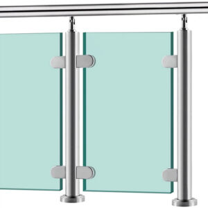
Most balcony railing projects reach fabrication with the concept signed off but the geometry unresolved — post centers assumed, corner treatments undiscussed, and mounting logic left for someone else to figure out later. When those gaps surface at shop drawing sign-off, the correction typically does not stay contained: changes to post positions force glass panel resizing, corner part reselection, and sometimes substrate preparation that was already underway. The decisions that prevent this cascade are not made during construction — they are made during design development, before fabrication drawings are released. Buyers who understand which geometry and fixing decisions must be frozen early, and why, are far better positioned to avoid the rework cycles that extend lead times and pressure adjacent trades.
Geometry decisions that must be frozen before release
Fabrication cannot start from an approved visual — it can only start from a defined geometry. The three decisions that most reliably block release when left open are post dimensions and handrail profile, railing height, and glass infill specification. Each feeds directly into fabrication drawings, and a late change to any one of them does not stay isolated: it triggers a redraw sequence that touches connected components and re-enters the approval queue.
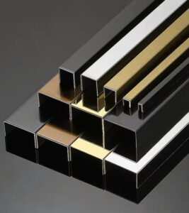
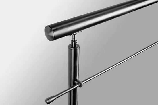
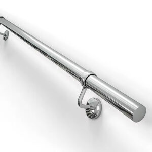
Post profile — whether round or rectangular — and the specific dimensions within each category determine how corner connections are detailed and what hardware is compatible. Handrail profile interacts with post cap selection, glass channel geometry, and in some systems, the infill attachment method. These are not aesthetic finishing touches to be confirmed at the end; they are dimensional inputs that fabricators need before any drawing can be produced with reliable accuracy.
Height is a compliance threshold as much as a design variable. The standard planning range runs from 850 mm to 1200 mm, with 1000 mm the most common working assumption for typical residential balcony conditions. Where the drop height exceeds 3 m, the minimum rises to 1100 mm — a condition that should be confirmed from structural drawings or site survey before any dimension is carried through to fabrication. Discovering this after glass panels have been cut means reordering, not adjusting.
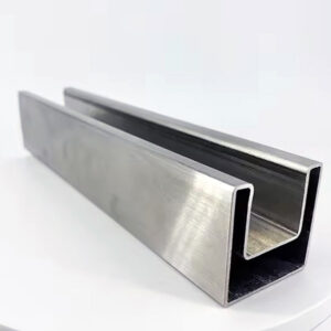
Glass infill specification closes the third gate. Laminated or toughened laminated glass at the correct thickness, with color and lamellae choices confirmed, must be defined before fabrication because glass lead times are independent of metalwork lead times. A late change here does not just delay the glass order — it may invalidate the channel dimensions already incorporated into post and rail drawings.
| Decision to Freeze | Required Definition | Risk if Unfrozen |
|---|---|---|
| Post dimensions & handrail profile | Round 42 mm dia; square 40×40 mm or 50×50 mm; handrail profile shape. | Fabrication cannot start; redraws trigger cascading design churn. |
| ارتفاع الدرابزين | 850–1200 mm (typically 1000 mm). If drop exceeds 3 m, minimum 1100 mm is required. | Non-compliance causes code failure or structural deficiency. |
| Glass infill specification | 8.76 mm laminated or toughened laminated glass; colour and lamellae choice. | Late changes force glass reordering, extending lead time. |
The practical review check at this stage is straightforward: if any of these three items carries a TBD, the design is not ready to release.
Post centers and corners that trigger redraw cycles
Post centers and corner details are two of the most commonly deferred decisions in balcony railing design, and they are the two most likely to force expensive redraws once fabrication has started.
Post center spacing is not freely adjustable after section lengths are determined. Centers are derived by dividing the total span symmetrically, and the section lengths that result must be consistent across the run. Asymmetric spacing is sometimes tolerated visually but creates asymmetric panel sizes that complicate glass cutting, increase material waste, and — for systems with mid-rail or infill elements — produce mismatched proportions that read as errors on the finished facade. Establishing post centers early, and checking them against the total span before releasing drawings, is a basic implementation discipline that is often skipped because it feels like a fabricator’s task rather than a designer’s one.
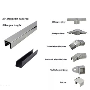
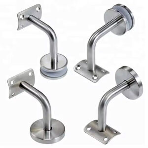
Corner treatment carries a more significant redraw risk. Stainless steel handrail systems typically include configured parts for corners — inside and outside angles, swept returns, and purpose-made junction pieces — and many of these parts are specific to both the profile type and the angle involved. An angle greater than 90 degrees, a non-standard return configuration, or a facade geometry that creates an irregular corner will require a specific component that must be identified, specified, and ordered as part of the initial package. Omitting the corner treatment from the design scope and expecting the fabricator to resolve it during production commonly results in a hold — the fabrication run pauses while the corner geometry is clarified, a part is sourced, and the drawing is revised. That hold is rarely isolated to the railing package alone.
The failure pattern here is predictable: corners are left out of the design scope because they are treated as transitions rather than components. By the time someone checks whether the corner part exists in the chosen system, the metalwork may already be cutting to length. Reviewing the corner condition for every change in run direction — before releasing fabrication drawings — is one of the more reliable ways to avoid this specific delay.
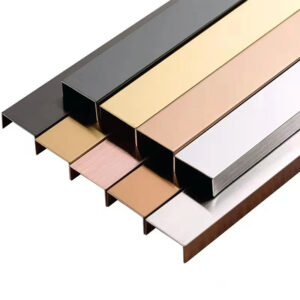
Round versus rectangular post design tradeoffs
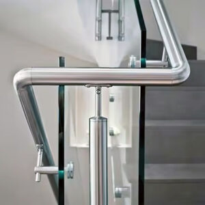
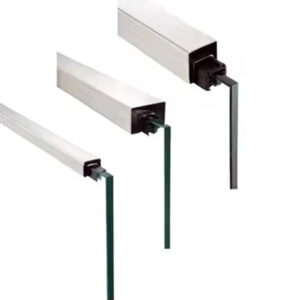
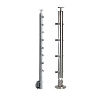
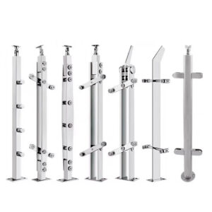
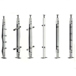
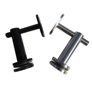
Post profile selection is treated as aesthetic in most early-stage design discussions, but by the time it reaches fabrication, it has already determined corner connection geometry, fixing hardware compatibility, and whether the facade rhythm reads as intended. Reversing the selection after order is placed means restarting glass sizing, reselecting corner parts, and potentially reconsidering substrate preparation.
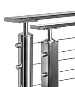
Round posts, typically in a 42 mm diameter for this application range, tend to simplify certain corner intersections because the circular section does not require alignment to a face plane. This makes them somewhat more forgiving where facade geometry is irregular or where the run changes direction at non-standard angles. The visual effect is a softer, more continuous line — a profile that reads well against curved elements or mixed architectural languages.
Rectangular posts in 40×40 mm or 50×50 mm sections produce a different outcome. The flat faces and crisp edges reinforce horizontal and vertical datum lines, which suits rectilinear facade compositions where the railing is expected to extend the architectural grid rather than contrast with it. The detailing consequence is that corners become more geometrically demanding: two flat-faced posts meeting at an angle require careful coordination to avoid awkward gaps or exposed cut ends, and that coordination must happen at the design stage, not during installation.
| أسبكت | Round Post (42 mm dia) | Rectangular Post (40×40 / 50×50 mm) |
|---|---|---|
| Corner detailing | Simplifies some intersections; often requires fewer special parts. | May need more detailed coordination to avoid complexity at corners. |
| Visual rhythm | Provides a softer, continuous appearance. | Delivers a sharper facade rhythm; suits rectilinear architectural language. |
| Facade integration risk | Less prone to visual clash with varied facade styles. | Wrong selection can clash with facade language and complicate corner connections. |
The procurement implication is that profile selection should be confirmed alongside the facade drawings review, not after. A عمود مستطيل من الفولاذ المقاوم للصدأ that fits the architectural intent of one elevation may create a corner detailing problem on a return facade that was never modeled in the same drawing set. Catching that conflict before fabrication is the decision that keeps both the aesthetic and the schedule intact.
Model handoff conflicts across project teams
The geometry may be agreed in principle between the architect and the client, but it is rarely modeled with the same assumptions by the architect, the railing supplier, and the installer. That divergence surfaces at shop drawing sign-off — the point where a supplier produces fabrication-ready drawings based on what was communicated, and the project team sees those drawings for the first time.
In a typical workflow, shop drawings are produced only after order confirmation and deposit, which means the first detailed resolution of slab edge offsets, corner conditions, and post center positions happens when reversing a decision is no longer cost-free. If the architect modeled the railing on the slab centerline and the supplier assumed a fascia-mounted detail, the elevation heights, glass panel sizes, and post positions will all be wrong in the shop drawings — and correcting them will require sign-off revision before production can start. That revision cycle is not the fabricator’s error; it is the result of handoff geometry that was never reconciled.
The structural consequence is that misinterpretation at this stage often cascades. Changing a post position to correct for the wrong slab edge offset also changes the glass panel width, which changes the corner configuration, which may change the hardware count. Each correction adds to the sign-off queue and pushes the production start date further out. The project teams most likely to avoid this cycle are those that reconcile slab geometry, mounting type, and corner conditions across all parties before the order is placed — not after drawings arrive.
A practical check before order confirmation is to ask the supplier to confirm in writing which inputs they are working from: slab edge position, mounting assumption, corner angle at each change of direction, and height at each section. If the answer comes back as a list of assumptions rather than confirmed figures, the handoff is not ready.
Fixing logic stability that defines design readiness
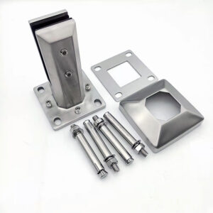
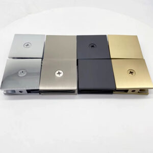
Fixing logic is the constraint that buyers most consistently underestimate, partly because it sits below the visible design and partly because the decisions involved feel like installation details rather than design decisions. They are not. Mounting type, substrate specification, and build class assignment each affect what is fabricated, not just how it is installed — which means they must be stable before fabrication drawings are released, not resolved on site.
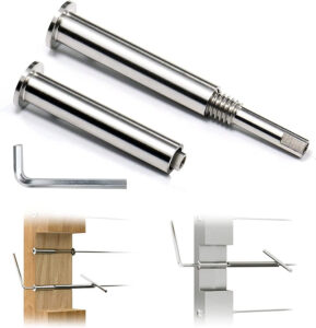
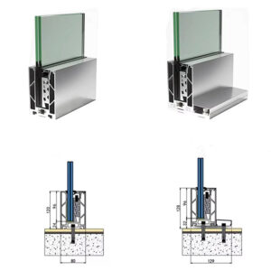
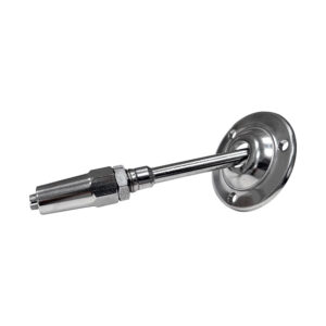
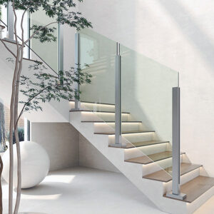
Mounting type — floor-mounted, top-mounted, fascia-fixed, or embed plate — is not interchangeable after the fact. Each option produces a different post length, a different base plate geometry, and different substrate preparation requirements. A floor-mounted post requires a core drill or cast-in plate at a specific position; a fascia-fixed post requires a bracket that may not be compatible with the slab edge thickness available. Changing mounting type after fabrication is ordered means remaking the posts, not adjusting them.
Substrate specification drives hardware selection and is substrate-specific rather than interchangeable. Fasteners appropriate for timber decking are not appropriate for concrete, and for outdoor exposure conditions — balconies in particular — corrosion class C4 is the appropriate benchmark for hardware specification in most exterior environments. Using underspecified fasteners in a corrosive exposure class does not fail visibly at installation; it fails over time, often without warning. ASTM E894-88 provides useful process-reference grounding for anchorage logic in permanent railing systems, and its principles reinforce why substrate and hardware specification should be treated as part of the structural design package, not a site decision.
Build class assignment connects structural validation to physical configuration. Higher load requirements demand closer post spacing, heavier glass, or additional structural checks — and the difference between a 1 kN/m and a 0.5 kN/m design load is not always resolved by simply adding more posts. In some configurations it changes the glass type, which changes the weight loading on the post and the base plate design. Leaving build class undefined until late in the process forces re-engineering of decisions that were already incorporated into drawings, often affecting items that were already in production.
| Fixing Decision | What to Define | Why Late Change is Costly |
|---|---|---|
| Mounting type | Floor-mounted, top-mounted, fascia-fixed, or embed plate. | Alters substrate preparation and fixing hardware; changes disrupt adjacent trades. |
| Substrate & hardware specification | Material (wood, concrete, etc.); fastener type; corrosion class (e.g., C4 for outdoor exposure). | Mismatched hardware leads to installation failure, corrosion, or rework on-site. |
| Build class & load requirement | Class A+ (1 kN/m) for higher-risk drops, Class A/B (0.5 kN/m) typical; assignment based on drop height. | Undefined class forces re‑engineering of post spacing, glass type, and structural checks. |
A درابزين شرفة من الفولاذ المقاوم للصدأ system designed with clear geometry and confirmed fixing logic does not require post-fabrication problem solving. The design is ready to release when mounting type, substrate class, and build class are all confirmed — not when the visual elevation looks complete.
The practical implication of everything covered here is that a balcony railing design package should be reviewed against a short list of confirmed decisions before it is released for fabrication: post profile and dimensions, railing height, glass infill specification, post centers and corner treatments, mounting type, substrate and hardware class, and assigned build class. If any of those items carries an assumption rather than a confirmed figure, it represents a deferred decision that will surface later at greater cost.
Before placing an order or requesting shop drawings, buyers should reconcile slab edge positions, corner conditions, and mounting assumptions with their supplier in writing. The goal is not to eliminate all revision — it is to ensure that any revision happens before fabrication starts, while its cost is still contained to a drawing change rather than a material change.
الأسئلة الشائعة
Q: What happens if the build class hasn’t been assigned by the time the supplier requests order confirmation?
A: The order should not be placed until build class is confirmed. Build class determines post spacing, glass thickness, and whether additional structural validation is required — and those variables are already embedded in the shop drawings the supplier will produce after deposit. Placing an order without a confirmed build class means the supplier will work from an assumption, and correcting that assumption after drawings are issued restarts the sign-off queue at a point when production time has already been consumed.
Q: If the slab edge geometry hasn’t been surveyed yet, is it safe to proceed with design development using assumed dimensions?
A: Design development can proceed for concept alignment, but assumed slab edge dimensions must not be carried into fabrication drawings. Slab edge position directly determines post length, base plate location, and elevation height — any one of which, if wrong, invalidates the glass panel sizes already drawn. The practical cutoff is order confirmation: by that point, actual slab edge positions must be confirmed and reconciled with the supplier in writing, or the shop drawings will be built on geometry that does not match site conditions.
Q: At what point does switching from a round post profile to a rectangular one become a cost-generating change rather than a design preference?
A: The profile switch becomes costly once glass sizing has been incorporated into drawings. Glass panel widths, channel dimensions, and corner part selection are all downstream of post profile — changing the profile after those elements are drawn means reissuing the glass specification, reselecting corner hardware, and resubmitting for sign-off approval. Before drawings are produced, the switch is a design decision; after drawings are in progress, it is a redraw trigger with material implications.
Q: Is a corrosion class C4 hardware specification always required for exterior balcony railings, or only in specific exposure conditions?
A: C4 is the appropriate benchmark for most exterior balcony environments, but the actual requirement depends on site-specific exposure factors — coastal proximity, industrial atmosphere, and humidity levels can each push a project toward or beyond C4. The risk of underspecifying is that corrosion failure is not visible at installation; it develops over time and can compromise anchorage integrity without obvious early warning signs. The substrate and exposure classification should be confirmed as part of the structural design package, not deferred to a site decision at installation.
Q: How should a buyer evaluate whether their project justifies the coordination effort required to freeze all geometry before fabrication, versus accepting a faster but less resolved design handoff?
A: The trade-off is not between effort and speed — it is between where the cost of unresolved decisions lands. A faster handoff that carries assumptions into fabrication does not eliminate rework; it relocates it to a stage where corrections affect cut material, glass already ordered, and substrate preparation already underway. Projects with straightforward runs and standard corner conditions carry lower risk from deferred decisions, but any project with irregular facade geometry, non-standard corner angles, or mixed mounting conditions will absorb the coordination cost one way or another. Front-loading that cost in drawing review is consistently cheaper than absorbing it in fabrication holds.