The railing post structural substrate is the construction that actually carries anchor loads back into the building — the concrete slab, the structural topping, the steel member, the structural masonry wall — and it is rarely the surface you see at the post base. Tile, stone, thin-set pavers, membrane, insulation, screed and plaster sit above it and change nothing about where the load has to go. The conditions that decide the mount are the total depth of finish build-up between the base plate and that structural layer, whether anything in that stack is void or compressible, the distance from the post centerline to the slab or wall edge, and what the project detail says the supporting construction actually is.
Until those four facts are established in writing, a base plate dimension and an anchor size are provisional. A post fixed to a finish layer looks identical, on day one, to a post fixed to structure.
Separate the Visible Finish From the Load-Bearing Backup
Treat every finish layer as non-structural until the project detail establishes otherwise. Tile, stone, pavers, bedding mortar, leveling topping, waterproofing membrane, insulation board and plaster are placed to shed water, spread wear or satisfy an appearance requirement. They may be hard, thick and perfectly sound underfoot and still be unable to hold an anchor against the prying action that a guard load creates at a post base.
That distinction is the one that anchor manufacturers make first. The Hilti Anchor Fastening Technology Manual, Version 2023, section 1.2.1, treats base-material properties as the starting point for anchor selection and capacity, and requires embedment to reach the actual base material rather than insulation or plaster. The same manual treats natural stone as a special material calling for case-specific technical consultation rather than a general rating — relevant wherever a stone paver or a stone cladding slab is the only thing visible at the post location. That guidance sits in a European technical framework and applies to Hilti’s own products; it is not a rating for the tile, paver or stone on your project.
The physical reason is straightforward. A guard load applied at handrail height arrives at the base plate as a moment, which resolves into tension on the anchors furthest from the applied load and compression on the bearing edge of the plate. Tension pulls the anchor straight out of whatever surrounds it, and a thin-set tile or a sand-bedded paver has neither the embedment depth nor the tensile continuity to resist it. The finish may resist the compression side perfectly well, which is exactly what makes a finish-only fixing feel solid when it is not.
So the working rule is to carry two separate descriptions of the same location: what the post sits on, and what the anchors reach. Those are the same thing only when the project detail says the structural slab or structural masonry is the exposed surface at the post.
Record Every Layer Between the Base Plate and Structure
| عنصر واجهة المستخدم | Project information to record | Decision enabled |
|---|---|---|
| Visible finish | Material and position within the build-up | Keeps the finish separate from the assumed load-bearing backup |
| Full build-up | Every intervening layer and the build-up depth | Shows the depth that the mount detail must address |
| Voids or compressible materials | Presence and position between the base plate and supporting construction | Flags a standoff condition that the mount detail must resolve |
| Structural backup | Supporting construction identified in the project detail | Establishes where the documented anchor load path must reach |
| Edge relationship | Edge offset shown with the post and anchor geometry | Tests the proposed geometry against the documented interface |
The record you need is a layer-by-layer description of the build-up at each post location, from the underside of the base plate down to the construction the project detail identifies as supporting. Each layer gets a material, a position in the stack, and a thickness; the stack gets a total depth; the location gets an edge offset.
Total build-up depth drives the mount decision more than any single layer does. It sets how far an anchor must pass through non-structural material before it reaches anything it can grip, which in turn sets the required anchor length and, where the finish cannot be cut through, whether the post must move to a different mounting condition entirely. A 15 mm tile over structural concrete and a 200 mm insulated roof build-up are both “tile on top” conditions and they lead to completely different details.
Voids and compressible layers need recording as presence and position, not just as thickness. A pedestal paver system, a drainage mat, a layer of rigid insulation, an unfilled cavity in a masonry wall: each one means the base plate is not bearing on the material the anchors grip. That is a standoff condition, and it changes how the connection behaves rather than simply making it longer.
Edge offset belongs in the same record because it is a property of the structural layer, not the finish. The finish may continue well past the slab edge, across a nosing or a coping, with no indication of where the concrete actually stops. Measure the post centerline to the structural edge and record it with the proposed base plate footprint and anchor pattern, so the geometry can be checked against the real condition rather than the visible one.
A practical point on sequence: this record is most useful before the finish goes down. The Feeney DesignRail overview describes a stone- or tile-covered concrete and roof-deck arrangement in which short stanchions are attached to structural members before the slab or membrane work proceeds. That is a named aluminum system example rather than a transferable detail, but the sequencing logic — resolve the structural connection first, bring the finish up to it afterward — is why the layer record wants to exist at shop drawing stage.
Trace Anchor Access Through Tile, Stone, Pavers, or Masonry
For each post, trace a specific physical path for every anchor in the pattern and establish whether it passes through the finish or around it. Those are the two outcomes, and each carries its own scope.
Passing through means coring or drilling the finish and bedding layers to reach structure, then setting an anchor long enough to achieve its embedment in the structural material alone — embedment measured from the top of the structural layer, not from the top of the tile. Through-finish work brings consequences that have to be named in the detail: the cut diameter, whether the finish material tolerates that cut without spalling or cracking, what reinstates the waterproofing where a membrane is pierced, and who makes good the finish around the sleeve or plate. Natural stone is the condition to flag earliest, because Hilti’s own manual pushes it toward case-specific consultation rather than a catalog value.
Going around means the post is positioned where the structural layer is already exposed or where the finish stops short, or the structural connection is made before the finish arrives and the finish is cut in around it. In masonry, going around often means finding the solid material: a cavity wall, a hollow unit, a rendered block face and a brick slip all put different thicknesses of non-structural or hollow material in front of the backup, and the anchor has to land in a bed that can hold it rather than in a face shell or a void.
The check that settles both cases is the same: does the planned anchor length, measured from the base plate down through every recorded layer, achieve full embedment inside the structural material, with the anchor pattern clear of the structural edge. If it does not, something has to change — anchor type, post position, base plate footprint, or the mounting method. Which of those changes is acceptable is a project decision, and on anything carrying guard loads the capacity assessment itself belongs with the anchor manufacturer’s data and the project’s design engineer.
Resolve Voids, Compressible Layers, and Edge Offsets
A void or compressible layer under the base plate has to be resolved in the detail, because it determines how the connection carries load rather than merely how deep the hole is. Hilti’s Steel-to-Concrete Connections handbook, version 1.0, June 2025, sections 2.1 and 6.5.2, states the principle plainly: anchors transfer attachment loads to the base material, and an ungrouted stand-off baseplate is separated from that material and connected only by the anchors. The handbook distinguishes that arrangement from a baseplate bearing through a grout layer. The point is that a gap is not a neutral dimension — it changes which elements carry the load. The handbook is steel-to-concrete guidance in a European design context and explains the load path; it does not prescribe a gap remedy, a grout instruction or an anchor size for your condition.
The consequence for a railing post is that the anchor shanks spanning the gap see bending in addition to tension and shear, and the effect grows with gap length. That is why “the base plate is sitting 40 mm proud because of the pedestal pavers” is a design question for the project engineer rather than a site adjustment. The same applies to a compressible layer: insulation or a drainage mat under the plate behaves as a gap once it yields, so recording it as a void-equivalent is more useful than recording its nominal thickness.
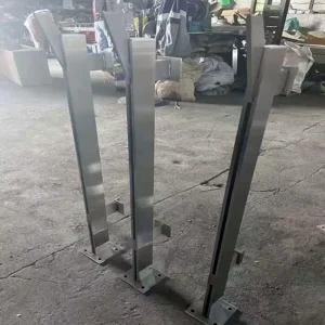
Edge offset resolves against the structural layer’s geometry alone. Reducing the base plate footprint, shifting the post inboard, or rotating the anchor pattern are the usual geometric moves; which one is available depends on the panel or infill layout the posts have to carry and on the spacing the design requires. Where none of them produces a workable condition, a different mounting method is the answer — a core mount set into the structural slab removes the plate footprint from the edge equation, and an adjustable base plate absorbs level variation in the structural surface without introducing a standoff gap. ألواح قاعدة مثبتة على السطح remain the simplest option precisely when the structural surface is exposed, flat and far enough from the edge that none of this arises.
One habit worth refusing: do not treat a base plate cover as the resolution of a standoff condition. It changes what you can see, not what the anchors are doing.
Coordinate Penetrations, Covers, Drainage, and Finish Repair
| Coordination item | Project detail to show | Decision supported |
|---|---|---|
| Anchor penetration | How the anchors pass through or around the finish build-up | Confirms whether the post and anchor geometry fits the documented interface |
| Cover or visible trim | Its relationship to the base plate, finish, and any standoff | Confirms that the visible treatment does not conceal an unresolved standoff condition |
| الصرف | Drainage condition at the post and finish interface | Confirms whether the mount detail accounts for drainage at that location |
| Finish removal, replacement, and repair | Access and finish work needed around the mount | Confirms whether the documented interface allows the planned finish work |
The interface details around the post need to be coordinated at the same time as the anchor geometry, because each of them can force the mount to move. Four items carry that weight: how the anchors penetrate or avoid the finish, what the cover or visible trim does, what happens to water at the post, and how the finish is removed and reinstated.
Penetration coordination has already been described as a path trace, and the drawing has to show it. A detail that shows a base plate and an anchor length but not the layers between them cannot be checked by the installer, the finish trade or the waterproofing subcontractor.
Covers and escutcheons are a finishing item. The Feeney DesignRail brochure describes base-plate covers as concealing screw heads and plates — a finishing touch, in the manufacturer’s own framing of its named aluminum system. Used that way they are perfectly legitimate. Used to hide the fact that a plate is standing off a paver with nothing resolved beneath it, the cover simply removes the evidence from view, which is the case where the detail needs to show the standoff and its resolution first and the cover second.
Drainage at the post interface deserves its own line in the detail. Every penetration through a finished horizontal surface is a potential water path, and a base plate on an exterior deck creates a shelf where water sits against the plate, the fasteners and the finish joint. In coastal or de-iced environments that standing water drives the corrosion exposure of the fixings and the stainless grade and finish selected for them. The detail should say where water goes at that location rather than leaving the slope and the sealing to be improvised on site.
Finish removal and repair is the access question nobody asks until a post has to come out. If the tile, stone or paver around the plate cannot be lifted and reset without damaging the surrounding field, then any future anchor replacement becomes a finish replacement. Worth checking whether the paver module can be lifted individually, whether spare finish material is being retained, and whether the cover or trim allows the plate fasteners to be reached without breaking the finish line.
Confirm the Structural Substrate Before Finalizing the Mount
Finalize the mount only when the project detail names the supporting construction at each post, the layer record shows the depth and content of everything between the base plate and that construction, every anchor in the pattern has a traced path reaching embedment in the structural material, the edge offset is measured from the structural edge, and any void or compressible layer is shown resolved rather than covered. Missing any one of those, the mounting hardware selection is a guess dressed as a specification.
The structural adequacy of the resulting connection — anchor capacity against the design guard load, and acceptance of the detail — is decided by the project’s design engineer and its approved procedure, not by matching a base plate to a hole pattern. Hardware selection serves that decision; it does not substitute for it.
For a useful conversation with a supplier about post hardware, have the mounting detail or section at each typical post location, the layer-by-layer build-up with total depth, the identified structural backup, the post centerline-to-structural-edge dimension, the infill type and post spacing driving the loads, the exterior exposure including any coastal or de-icing condition, and the specified stainless grade and finish. With those in hand the discussion moves directly to whether a surface mount plate, an adjustable plate or a core mount suits the condition, and what the base plate footprint and anchor pattern need to be. Without them, the honest answer any supplier can give is a list of the same questions.
الأسئلة الشائعة
س: Can tile, stone, pavers, or topping be treated as the structural substrate for a railing post?
A: Only if the project detail explicitly identifies that construction as the load-bearing backup. Otherwise, treat it as part of the finish build-up and trace the anchor load path through every intervening layer to the documented supporting structure.
س: What should be compared before choosing a surface mount, adjustable base plate, or core mount route?
A: Compare the identified structural backup, total build-up depth, anchor access, voids or compressible layers, edge offsets, drainage, and finish-repair access. A route should move forward only when its post and anchor geometry can be detailed through the recorded interface without relying on an assumed finish layer.
س: Can a cover plate solve a gap between the base plate and the supporting construction?
A: No. Visible trim can finish the interface after the standoff condition has been resolved, but it should not conceal an unsupported gap, void, or compressible layer. Show both the structural resolution and the cover relationship in the mount detail.
س: When is a railing post shop drawing ready for final mount selection?
A: It is ready when the structural substrate, complete layer build-up, anchor route, edge relationship, and required interface work are all shown consistently. If any of those items remains unknown, record the exact open condition and hold the final mount detail until the project-specific design is confirmed.
س: How should future finish replacement affect the post-mount detail?
A: Define how the finish can be removed, replaced, and repaired around the post before finalizing the interface. Coordinate that access with the base plate, penetrations, visible trim, and drainage so planned finish work does not leave the structural load path or standoff condition ambiguous.