Selecting a post mounting method after the infill type is already confirmed is one of the most common sequencing errors in stainless steel railing projects. It surfaces late — often during substrate review or waterproofing inspection — and the rework it triggers ranges from re-specifying anchor hardware to abandoning a base shoe system entirely when the slab turns out to be too thin. The core issue is that cable and glass infills impose structurally different demands on the post, and the mounting detail that handles one load condition may not reliably handle the other without explicit verification. Understanding where those demands diverge, and where a shared mounting platform can be justified, is what determines whether the structural and aesthetic choices made early in design remain defensible through installation and inspection.
Why Infill Type Changes Post Demand
The load character of cable railing and glass railing is not interchangeable, and the post is where that difference becomes a structural problem or a non-issue depending on how early it is recognized.
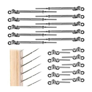
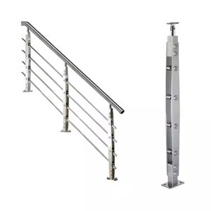
Cable infill generates a continuous outward tension force. End posts bear the greatest share — they must anchor the full tension of each cable run — but intermediate posts are also subject to sustained lateral pull rather than intermittent wind loading alone. The consequence of underestimating this is specific: if a post yields even slightly under sustained cable tension, the cable loses its set and sag becomes visible across the run. That sag is not just an aesthetic issue; it becomes a code and inspection flag, and correcting it typically means retensioning or replacing hardware after installation is complete.
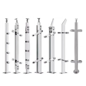
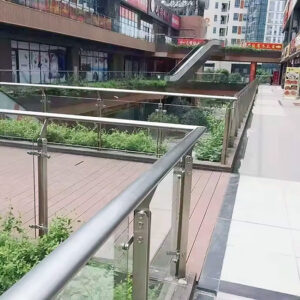
Glass railing posts carry a different load profile. The primary concern is lateral moment from wind and handrail forces, and the panel-to-post connection governs how much of that moment transfers into the substrate. Post-mounted glass systems benefit from the post itself contributing to structural stiffness, which changes what the glass panel alone must resist — a point with direct implications for panel thickness and material cost that becomes relevant during procurement.
Typical post spacing reflects these differences, though the figures used in practice should be treated as planning criteria subject to structural calculation rather than universally fixed limits.
| Tipo de preenchimento | Espaçamento típico entre colunas | Key Post Design Challenge |
|---|---|---|
| Corrimão de cabos | 4 ft on-center | Posts must resist continuous outward cable tension without yielding; any deflection leads to cable sag and code/inspection issues. |
| Guarda-corpo de vidro | 5 ft on-center | Posts carry intermittent wind and handrail loads while supporting glass panels; stiffness limits panel deflection and can reduce glass thickness needed. |
Designing for the right post spacing without accounting for the load direction — or defaulting to one set of spacing assumptions across both infill types — creates a review gap that often goes undetected until the railing is loaded or inspected.
Attachment Failures From Shared Unverified Details
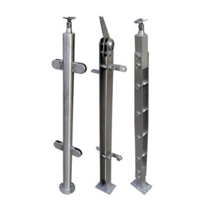
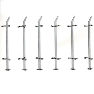
Reusing a post base detail across cable and glass runs on the same project is not inherently wrong, but treating it as a default without reviewing the underlying load case is a consistent source of progressive failure. The mechanism is straightforward: a mounting assembly engineered for lateral moment loads from glass panels does not automatically resist the sustained outward tension that cable infill applies to the same anchor group. The fastener pattern and base plate geometry that satisfy one condition may leave the other underchecked.
What makes this failure pattern difficult to catch early is that inadequate structural support often produces movement that is subtle at installation and worsens with time and use. Wobble at the post base does not announce itself at punch-list; it develops as fasteners work loose or blocking compresses under repeated loading. By the time the distress is visible, the fix requires either re-anchoring or reinforcing substrate framing that may now be partially enclosed.
The same review gap applies to fastener penetration. Surface-mounted post bases on wood decks depend on lag screws or through-bolts reaching into deck joists or solid blocking — not just into decking material. If the blocking was sized or placed for the cable infill load case, it may not be adequate when glass panels with their higher lateral moment demand are added to the same structural bay. Verifying that the blocking and fastener specification covers both load cases before finalizing the mounting detail is a pre-fabrication check, not a site adjustment.
Shared mounting details across infill types should be treated as requiring explicit sign-off on both load cases, not as a convenience default that saves one round of calculation.
Stiffness Versus Visual Weight and Installation Speed
The choice between a post-mounted system and a base shoe configuration is frequently framed as an aesthetic decision, but it carries structural and procurement consequences that become concrete when the substrate is constrained or the material budget is fixed.
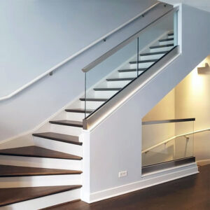
Post-mounted glass railing provides maximum structural rigidity because the post contributes directly to resisting lateral loads — the glass panel does not carry the full structural burden alone. That load sharing has a downstream effect on the glass specification: panels in post-mounted systems can, depending on the configuration and manufacturer’s engineering, use thinner material than a comparable base shoe installation. This is a manufacturer-specific optimization, not a code-exempt shortcut; glass thickness must still satisfy applicable load requirements under the governing structural standard. However, when procurement sequencing is tight, the difference in panel cost between systems is a real consideration rather than a marginal one.
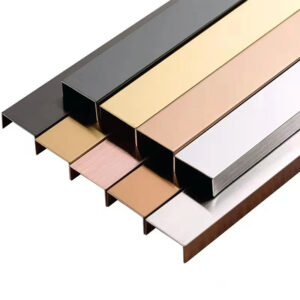
Base shoe U-channel systems achieve a continuous, frameless glass surface precisely because there are no visible posts interrupting the sightline. The structural trade-off is that the glass must carry loads the post would otherwise absorb, which pushes panel thickness and cost upward. Installation speed also differs: a U-channel system involves precise channel setting and alignment before glass is placed, while post-mounted systems allow glass to be fitted and adjusted relative to posts that are already anchored. Neither sequence is universally faster — it depends on crew experience and substrate conditions — but the frameless aesthetic comes with a more demanding installation tolerance.
The comparison between the two approaches is clearer when the structural, cost, and visual variables are read together.
| Sistema | Desempenho estrutural | Glass Panel Requirements | Aesthetic Result | Implicações de custo |
|---|---|---|---|---|
| Post-Mounted Glass Railing | Posts provide maximum structural rigidity; assist in carrying wind/handrail loads. | Can use thinner, less expensive glass. | Visible posts periodically interrupt the sightline. | Lower glass material cost; post material cost applies. |
| Base Shoe (U-Channel) Glass Railing | Frameless continuous channel supports glass; relies on glass panel for structural performance. | Requires thicker, stronger glass to handle loads independently. | Continuous glass surface with no visible posts; ultimate frameless look. | Higher glass material cost; no post but channel system required. |
The practical implication is that selecting the base shoe for its appearance while the substrate is borderline for anchor depth, or choosing a post-mounted system to control glass cost while the owner expects a frameless aesthetic, produces a conflict that surfaces in either structural review or client acceptance — neither of which is an inexpensive point to resolve.
Structural Coordination Before Infill Approval
Substrate confirmation is not a step that follows infill approval — it is a prerequisite for it. Projects that lock in the infill type and then discover the substrate cannot support the required mounting system face compressed timelines and either redesign or structural remediation as the available options.
The clearest threshold here involves base shoe systems on concrete. Anchor embedment depth of at least 3 inches into concrete, with a minimum slab thickness of 4 inches, represents planning criteria from manufacturer guidance; the actual required values must be confirmed against project-specific specifications and load calculations. When the concrete is thinner than that threshold — a thin overlay or topping slab, for example — base shoe installation may not achieve adequate pull-out resistance, and a post-mounted system becomes the structurally justified choice regardless of aesthetic preference. These figures come from manufacturer-defined requirements rather than a single universally applicable code provision, so confirming them against the actual system being specified is part of the review, not an assumption that can be carried forward unchecked.
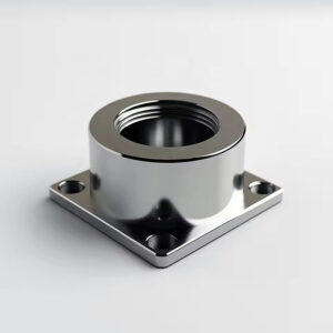
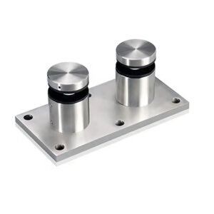
Surface-mounted post bases introduce a separate risk on waterproofed decks. Fasteners that penetrate the deck membrane to reach joists or blocking below create potential moisture intrusion points. In humid climates or jurisdictions where building codes mandate fascia mounting to preserve membrane integrity, surface mounting is not a preference question — it is a compliance issue. Fascia mounting, which locates the post base against the rim joist rather than the deck surface, requires blocking material attached inside the rim joist for reinforcement, and that blocking must be sized for the infill load case being installed. Placas de base resistentes designed for structural fascia applications carry load differently than surface-mount plates, and substituting one for the other without checking the load path is a review gap, not an installation shortcut.
Post-mounted systems offer broader substrate compatibility — concrete, steel, and reinforced wood — compared to base shoe systems, which are limited to concrete or steel meeting minimum thickness criteria. That flexibility is real, but it does not eliminate the requirement to verify pull-out and shear capacity for the specific anchor pattern and infill load case under ASCE/SEI 7-22 load combinations. Substrate versatility is a planning advantage, not a structural guarantee.
| Método de montagem | Suitable Infill | Substrate Compatibility | Requisito estrutural crítico | Important Code/Limitation |
|---|---|---|---|---|
| Surface Mount (Top) | Cable, Glass | Wood deck with accessible joists | Fasteners must penetrate deck joists or blocking; blocking must resist pull-out. | Punctures waterproof membrane; some jurisdictions mandate fascia mount to prevent moisture intrusion. |
| Fascia Mount (Side) | Cable, Glass | Wood deck with rim joist | Requires blocking material attached to inside of rim joist for reinforcement. | Preserves membrane integrity; may be required by code in humid climates. |
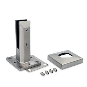
| Base Shoe (U-Channel) | Glass only | Concrete (min. 4″ thick), steel | Anchor embedment minimum 3″ into concrete; channel must resist wind moment loads. | Not suitable for thin overlays or wood; post mount recommended when concrete <4″. |
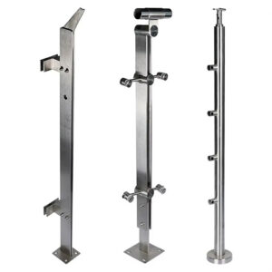
| Post Mount (General) | Glass, Cable | Concrete, steel, reinforced wood | Base plate and anchors must accommodate infill-specific load direction: outward tension (cable) or lateral moment (glass). | Verify slab edge or deck framing can support the proposed loads before infill approval. |
The sequencing implication is direct: infill type, mounting method, and substrate adequacy should be confirmed as a coordinated package, not as three sequential decisions where each assumes the previous one was already resolved.
Conditions for One Mount Across Glass and Cable
A single mounting platform serving both glass and cable infill runs on the same project is achievable, but the condition for approving it is specific: the assembly must be engineered to resist both load cases simultaneously, not just verified against whichever case was calculated first.
Cable infill imposes continuous outward tension — a load that acts along the cable plane and requires the post and its base to resist pull-out and lateral displacement without yielding. Glass infill imposes lateral moment loads from wind and handrail forces acting perpendicular to the post. These are different force directions and different demand characters. A base plate and anchor group sized for the cable tension case may not have adequate moment arm or fastener distribution for the glass panel case, and the reverse is equally possible. Under ASCE/SEI 7-22 load combinations, both conditions need to be checked explicitly; the higher of the two demand cases does not automatically govern unless the load directions and anchor geometry happen to align in a way that makes one case bounding in all relevant modes.
Before approving a common post and base plate for both infill types, the relevant questions are whether the base plate geometry distributes load adequately for both cases, whether the anchor pattern and embedment satisfy pull-out, shear, and combined loading for both infill demands, and whether the post section itself has sufficient stiffness to limit deflection under sustained cable tension without affecting either cable set or the adjacent glass panel. ASTM E935-21 provides a testing framework for verifying the performance of permanent metal railing assemblies, but its applicability to a specific dual-infill configuration depends on whether that exact assembly has been tested — compliance cannot be assumed based on testing of a single-infill variant of the same hardware.
The practical check for this condition is documentation: the engineering record for the common mount should explicitly reference both infill load cases and demonstrate adequacy for each. If the record covers only one, the shared detail is not yet approved for dual use regardless of how it looks in the field.
For projects combining glass and cable runs, reviewing selection factors specific to each infill type before committing to a shared mounting strategy helps surface conflicts earlier. Frameless vs post-mounted stainless steel glass railing systems covers structural and aesthetic factors relevant to the glass side of that coordination.
Mounting method selection is an early structural commitment, not a hardware detail finalized at procurement. The substrate type and depth, the infill load character, the waterproofing strategy, and the project’s visual intent all interact in ways that make late-stage substitutions expensive — whether that means switching from base shoe to post-mounted when the slab falls short, or reworking a shared mount detail that was never checked against both cable tension and glass moment demands.
Before infill is approved, confirm that the proposed mounting method is compatible with the actual substrate, that the anchor and blocking design covers the specific load case the infill imposes, and that any shared post base across infill types has explicit engineering documentation for both conditions. Those three checks define the difference between a mounting decision that holds through inspection and one that produces rework after the railings are loaded.
Perguntas frequentes
Q: My deck edge is cantilevered and there’s no rim joist for fascia mounting. Are surface mounts still a viable option?
A: Yes, but only if the base plate is anchored into solid blocking that transfers loads back to the main framing, not just the cantilevered decking. Cantilevered edges often lack the direct joist support that standard surface mounts require, so additional blocking or a custom steel bridging plate is typically needed to prevent post movement from developing over time.
Q: After I’ve confirmed the substrate meets the required thickness, what documentation should I request before ordering the mounting hardware?
A: Request an engineering evaluation from the manufacturer that explicitly covers the post assembly for both infill load cases — cable tension and glass panel moment — using your project’s actual post spacing and substrate details. This confirms the mounting detail was verified for the specific load demands, not just a generic product specification.
Q: At what concrete slab thickness does a base shoe system become structurally comparable to a post-mounted glass railing?
A: There isn’t a single threshold where the two become interchangeable. When concrete exceeds 6 inches and anchor embedment depth can comfortably exceed 4 inches, a well-designed base shoe channel may satisfy the same wind-load requirements, but the glass panel thickness and deflection behavior still differ under load, so a full structural comparison is required to confirm equivalence.
Q: When building codes don’t mandate a specific type, is surface mounting or fascia mounting more cost-effective on a wood deck?
A: Surface mounting is generally less expensive upfront because it avoids the labor and material for the blocking reinforcement that fascia mounting demands. However, if the deck has a waterproofing membrane that must remain intact, the long-term cost of a moisture-related failure from surface penetrations can easily outweigh the initial savings, making fascia mounting the cheaper option over the life of the assembly.
Q: Are heavy-duty base plates worth the investment for a standard residential cable railing, or do regular plates suffice?
A: For typical residential runs with 4-foot post spacing and moderate cable tension, standard base plates designed to the load case are usually adequate. Heavy-duty base plates like those in ESANG’s heavy duty range become cost-justified when end posts carry high tension from long cable spans, or when the substrate offers limited anchor distribution — thin concrete or minimal blocking — where the extra stiffness reduces maintenance and prevents progressive loosening.