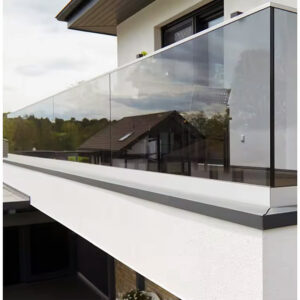
Fabrication drawings for a Juliet balustrade regularly arrive on site before anyone has confirmed whether the wall build-up can actually accept the brackets at the specified projection. When that gap surfaces during installation, the options narrow fast: relocate fixings into zones that compromise waterproofing continuity, oversize brackets to bridge the offset, or strip back cladding that has already been applied. The judgment that prevents all three of those outcomes is deciding the support method and bracket positions before the envelope design is locked, not after. What follows gives contractors and architects the layout checks needed to make that call with confidence before anything goes to fabrication.
Opening constraints that shape the Juliet layout
The starting reference point for any Juliet layout is the actual clear opening dimension, measured after all finished surfaces are applied — not the rough structural opening. That distinction matters because facade insulation, cladding boards, render systems, and window reveal trims all reduce the usable fixing width and shift the effective face of the wall outward. Teams that take bracket positions from structural drawings without accounting for the finished build-up frequently discover that their specified fixing centers land in composite material rather than substrate, or that the bracket projection needed to clear the cladding face exceeds what the original detail assumed.
Projection depth is the variable that connects opening size to structural adequacy. A shallow projection keeps the balustrade visually flush with the facade and reduces lever arm loading on wall fixings, but it demands that the face of the substrate is precisely where the build-up drawing says it is. A deeper projection can accommodate more facade variation, but it increases the bending moment at the wall bracket and puts more demand on anchor pullout capacity. Neither is universally correct — the right choice follows from the actual wall section, not from what looks cleanest in elevation.
The practical check at this stage is to confirm three inputs before bracket positions are drawn: the finished face of the facade at the fixing zone, the minimum substrate depth available for anchors, and the clear opening width between door frame reveals after all trim is in place. Any one of those figures left unconfirmed at layout stage will likely surface as a conflict during installation.
Door swing and facade build-up conflicts
Door type is a layout input that determines bracket placement zones, and resolving it early is what separates a clean detail from one that requires field modification. The critical distinction is between a sliding door, which parks parallel to the opening and creates no swing obstruction, and an inward-opening French door, which sweeps across a floor arc that can directly conflict with where brackets need to land.
| Door Type | Swing Direction | Bracket Placement Constraint | Risco se não estiver claro |
|---|---|---|---|
| Sliding door | None (slides parallel) | Bracket placement not obstructed by door swing | Low; still confirm opening dimensions |
| Inward‑opening French door | Inward | Brackets must avoid door swing path | Rework or compromised guardrail function |
For inward-opening French doors, bracket positions must be confirmed against the full swing path before fabrication drawings are approved. The conflict is rarely visible in plan unless someone has actually overlaid the door swing arc onto the bracket layout — and that step is often skipped when the balustrade detail is handled separately from the door schedule. When a bracket does land inside the swing path, the field fix is usually to shift it outward along the wall, which may push it into a weaker fixing zone or reduce the guardrail’s structural span to an unacceptable width.
Wall build-up compounds this further. On facades with external insulation or rain-screen cladding, the effective fixing face is set back from the bracket’s outermost point by the build-up thickness. If that thickness is variable — common with uneven masonry or site-applied render — bracket projection depths will vary across the width of the opening, and any dimension taken from a flat-face assumption will be wrong at some fixing points. Confirming actual build-up depth at each bracket location before layout is finalised is the check that prevents this from becoming a fabrication problem.
Face fixing compared with floor edge support
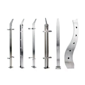
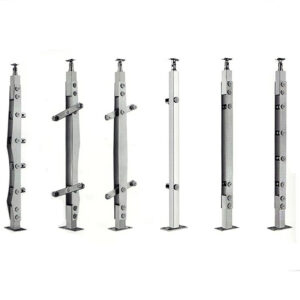
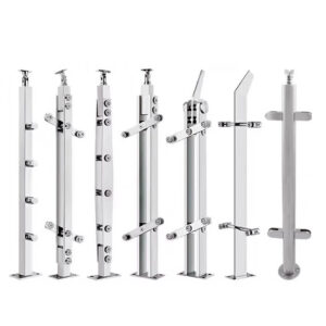
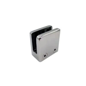
Face-fixed balustrades attach to the wall surface directly above or adjacent to the door frame, keeping the floor threshold clear and preserving the full opening width. Floor-edge configurations locate the support at the structural floor level, either through a base plate or core-mount system, which shifts the load path downward but introduces a new set of constraints around the floor edge condition, drainage falls, and threshold detailing.
Face fixing is often favoured on Juliet configurations because it avoids disturbing the threshold zone and keeps the bracket count lower. That advantage holds when the substrate is consistent, the fixing zone is accessible for inspection, and anchor embedment depth is predictable. It becomes a less reliable choice on facades with variable masonry, cavity construction without an accessible inner leaf, or composite cladding systems where the structural backing depth is inconsistent across the bracket span. ASTM E894-88 provides a useful reference framework for thinking about anchorage performance expectations — the principle that railing anchorage must resist defined lateral and vertical loads in a consistent, testable way applies directly to bracket pull-out and bending resistance in face-fixed Juliet installations, regardless of whether that specific standard governs the project.
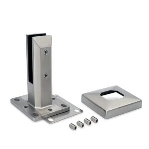
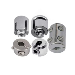
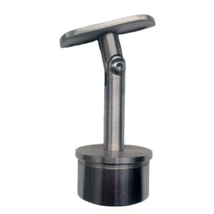
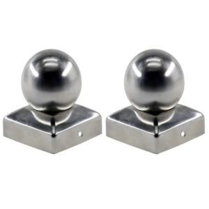
Floor-edge support, by contrast, requires that the floor structure at the door threshold can carry point loads without affecting the threshold seal or drainage path. On upper-floor installations over occupied space, that load path often needs to be traced through the slab edge and confirmed with the structural engineer before bracket positions are committed. Core Mount Base Systems designed for floor-edge installation address the load transfer geometry at that junction, but the floor condition still needs to be verified before the support method is selected.
The trade-off is this: face fixing demands more from the substrate and tolerates less variation in wall build-up, while floor-edge support demands more from the threshold and drainage detailing. Projects with clean masonry substrates and straightforward cladding will often suit face fixing. Projects with multi-layer facades, drainage-sensitive thresholds, or ambiguous substrate depths warrant a closer look at floor-edge options — or a re-evaluation of whether a Juliet configuration is the right choice at all.
Waterproofing failures around late support decisions
The failure pattern here is predictable and consistently expensive: the support method for the balustrade is treated as a finishing trade decision, so it gets confirmed after the waterproofing membrane and drainage details are already designed. When brackets then need to penetrate the facade at positions that were not included in the waterproofing sequence, the sealing strategy becomes a retrofit rather than an integrated detail, and retrofit seals at facade penetrations under dynamic load are among the less durable joints in any external envelope.
The specific risk is not simply that penetrations exist — it is that penetrations made after waterproofing design are more likely to cross membrane laps, land at drainage channels, or intersect with cavity closers that were positioned without them in mind. Each of those conflicts requires a site-specific seal solution that may not be reviewed by the envelope designer, may not be tested under the same conditions as the rest of the membrane, and may not be visible for inspection once cladding is applied. Defects that emerge from this sequence often appear in service rather than during practical completion inspections, which makes attribution and remediation both slower and more costly.
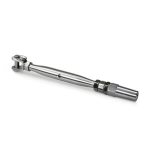
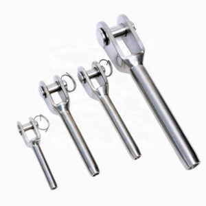
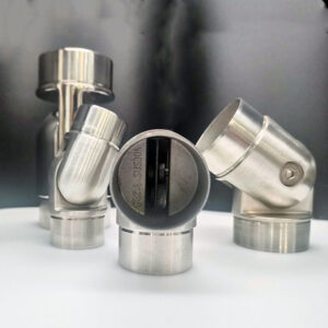
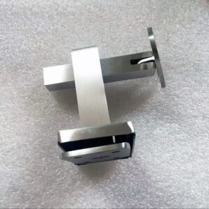
The sequencing principle is straightforward: bracket positions and fixing penetration zones must be resolved before the waterproofing detail is drawn, not after. That means the balustrade layout — including support method, bracket spacing, and projection depth — needs to be a live input during envelope design, not a subsequent overlay. For projects using glass mounting adapters or flush-face fixing hardware, the fixing footprint and any required backing plate dimensions should be available to the waterproofing designer at the same stage as window head and sill details.
Where that sequencing has already been missed and bracket positions are being confirmed after waterproofing is designed, the practical response is to map proposed fixing locations against the membrane drawing before any holes are made, identify conflicts explicitly, and have the envelope designer specify the remedial seal approach in advance rather than leaving it to the installing trade.
Load path clarity that makes a Juliet scheme workable
A Juliet balustrade is structurally workable when the forces applied to it — lateral load from a person leaning against the glass or rail, vertical load from someone gripping the top rail, and any dynamic or impact load — can be traced through an identifiable, connected path to a structural element capable of resisting them. Where that path is ambiguous or depends on elements that have not been confirmed, the scheme carries latent risk that fabrication and installation cannot resolve.
The practical check is to ask, for each bracket position: what is it fixed to, how deep are the anchors in that substrate, and what is the fixing’s resistance to both pull-out and bending? On straightforward masonry walls, this is usually verifiable from the wall section and a standard anchor manufacturer’s data table for the substrate type. On composite facades with insulation, cavity, and inner leaf, the answer is less immediate — and assuming the fixing lands in solid masonry when it may land in insulation board is a failure mode that appears frequently in post-installation remediation work.
OSHA 1910.29 reflects the broader principle that guardrail systems must be designed and installed to resist defined loads from identifiable directions — a process-level expectation that applies whether the project is commercial or residential and regardless of which specific standard governs the jurisdiction. Treating load path confirmation as a pre-fabrication review step, rather than something verified at installation, is what keeps the Juliet scheme from becoming a structural liability that only becomes apparent when the balustrade is in service.
One condition that consistently undermines load path clarity is oversizing the bracket to compensate for an uncertain fixing position. A deeper or heavier bracket can increase the lever arm, raise the bending demand at the wall anchor, and shift more load into a smaller number of fixings — the opposite of the mitigation it appears to offer. If the wall section cannot support a standard bracket layout at the specified spacing, the more defensible response is to re-evaluate the support method or opening configuration rather than to upsize hardware in place.
The decision that protects project cost and envelope performance on a Juliet scheme is not which balustrade system to specify — it is whether the wall section, anchor zones, and waterproofing sequence can genuinely support the configuration before fabrication begins. That judgment requires confirmed figures: finished facade depth, anchor substrate depth at each fixing location, door swing geometry, and bracket positions mapped against the waterproofing layer sequence.
Before sending drawings for fabrication, confirm that each of those inputs has been resolved and that the support method chosen — face-fixed or floor-edge — reflects the actual wall condition rather than a default preference. A balaustrada de varanda system specified against accurate layout data will install cleanly; one specified against assumptions will generate rework costs that arrive at the worst possible project stage.
Perguntas frequentes
Q: What if the substrate depth varies across the bracket span — is a Juliet configuration still viable?
A: It depends on whether the variation exceeds the bracket’s tolerance for inconsistent projection depth. If substrate depth changes significantly between fixing points, the load path becomes uneven and anchor performance across the span can no longer be verified from a single wall section reference. In that situation, either each bracket position needs individual substrate confirmation before layout is finalised, or the scheme should be re-evaluated — a Juliet configuration is only defensible when the wall can carry the load path consistently, not when it can at most positions.
Q: Once bracket positions and the support method are confirmed, what should happen before the fabrication drawing is released?
A: The confirmed bracket layout should be overlaid against the waterproofing membrane drawing to verify that no fixing penetration crosses a membrane lap, drainage channel, or cavity closer. That check needs to be completed — and any conflicts resolved with the envelope designer — before the drawing is released for production. Releasing fabrication drawings before that overlay step is done is the sequence that creates retrofit seal problems in service.
Q: At what point does a multi-layer facade make floor-edge support the better choice over face fixing?
A: When the composite build-up makes substrate depth ambiguous at any bracket location, floor-edge support becomes more defensible than face fixing. Face fixing relies on predictable anchor embedment across every fixing point — if insulation, cavity, or variable masonry means that embedment depth cannot be confirmed without opening up the wall, the substrate condition does not meet the standard face fixing requires. Floor-edge support moves the load path to the slab edge, where the structural condition is typically easier to confirm, though it introduces its own threshold and drainage constraints that still need to be verified.
Q: Is a Juliet balustrade a weaker regulatory position than a full balcony guardrail on a commercial project?
A: Not inherently, but it carries more pre-fabrication risk if the load path has not been explicitly confirmed. A full balcony guardrail typically connects to a structural floor edge with a more traceable load transfer geometry. A Juliet scheme depends entirely on wall anchor performance, and OSHA 1910.29’s expectation that guardrail systems resist defined loads from identifiable directions applies equally — without the floor-edge redundancy a conventional balcony provides. The regulatory position is equivalent only when anchor pull-out and bending resistance have been verified at each bracket location against the actual substrate, not assumed from the wall type.
Q: If door type hasn’t been confirmed yet, is it safe to begin dimensioning bracket positions from the opening width alone?
A: No — dimensioning from the opening width before door type is confirmed will produce bracket positions that may need to be relocated once the swing arc is mapped. For inward-opening French doors in particular, brackets placed at standard spacing from the door frame reveal can land directly in the swing path, and relocating them after layout is approved usually means moving into a weaker fixing zone or reducing the structural span between brackets. Door type needs to be a resolved input at the same stage as the clear opening dimension, not a detail confirmed later in the door schedule.