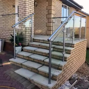
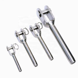
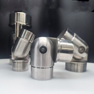
A handrail run is rarely one component decision; it is a sequence of coordinated decisions that only make sense once the full path, its supports, and its endpoints are known together. Before a buyer can compare tube profiles, bracket styles, or post bases, the project needs to establish what the run actually covers, where it changes direction or elevation, and which authority governs its gripping surface and clearances. Skipping that sequencing step is what turns a straightforward handrail order into a mismatched delivery.
Handrail-run information needed before selecting components
| Scope item | Project information to establish | Selection consequence |
|---|---|---|
| Travel path and landings | Lay out the covered route and each landing. | Defines the run geometry before tube, bracket, or post families are selected. |
| Turns, terminations, and elevation changes | Locate every turn, endpoint, transition, and change in elevation. | Identifies where returns and transitions must be coordinated. |
| Project coverage and adopted requirements | Confirm the actual project coverage and the requirements currently adopted for it. | Determines which gripping-surface, clearance, continuity, and extension provisions apply. |
| Mounting approach | Identify the wall-mounted and post-mounted portions of the run. | Establishes the support interfaces that must be coordinated. |
| Substrate and finish build-up | Verify the substrate and finish build-up at each support condition. | Keeps bracket and base selection tied to the actual condition; structural connection decisions remain with the responsible project parties. |
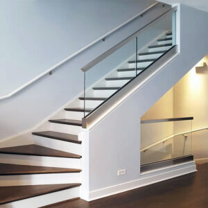
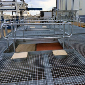
Component selection depends on first establishing the shape of the run, not on choosing a bracket or tube family and working backward. The travel path, including every landing, turn, termination, and change in elevation, defines the geometry that tube lengths, joint locations, and bracket spacing must follow. Where a run includes a single straight flight, the component list stays relatively simple; where it includes multiple turns, landings, or level changes, the number of returns, transitions, and support points multiplies, and each one becomes a point where a component family decision has to be made deliberately rather than assumed.
This is also the stage where the applicable requirements get identified, not applied. Different projects fall under different adopted accessibility and life-safety provisions, and the same physical run can be subject to different gripping-surface, clearance, continuity, and extension expectations depending on which requirements the project has adopted and which portions of the building the run actually serves. The Access Board Guide’s chapter on stairways explains gripping surface, clearance, continuity, and extension provisions for covered US accessible stairs, but that scope applies only where the project falls within that coverage; a run outside that coverage, or a project in a different jurisdiction, needs its own confirmed basis before anyone treats those provisions as binding.
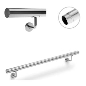
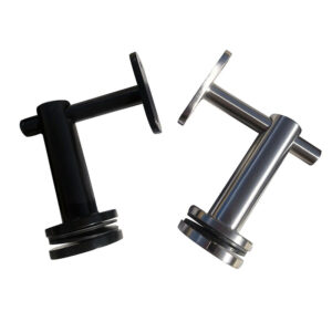
Mounting approach is the other input that has to be settled early, because wall-mounted and post-mounted portions of the same run create different support interfaces and often different component families even within a single continuous handrail. A run that transitions from a wall-mounted segment to a post-mounted segment at a landing is not a single bracket decision; it is two interface decisions that have to be coordinated at the transition point.
Substrate and finish build-up at each support location is the last piece, and it is often the one most likely to be assumed rather than verified. A bracket or base selected against a drawing dimension can still be wrong on site if the actual wall or post structure, or the finish build-up applied over it, differs from what the drawing assumed. Confirming the real substrate condition before committing to a bracket and base pairing keeps the component selection tied to what will actually be installed against, while the structural adequacy of that connection remains a decision for the responsible project parties, not an assumption built into the hardware order.
Gripping surface, path geometry, clearances, and changes in elevation
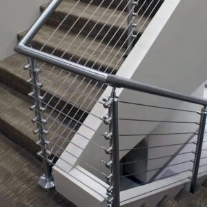
Gripping surface, path geometry, wall or post clearance, and changes in elevation are not independent specifications; they interact along the same run, and a change in one changes what the others need to be. A handrail’s gripping surface has to remain continuously graspable along the full path the reader lays out, which means every turn and every change in elevation is a point where continuity can be broken if the component selection does not account for it. Where a run includes a continuous change in slope, such as a stair-to-landing transition, the gripping surface and the clearance behind it have to carry through that transition without an interruption that forces the hand to release and re-grip.
Clearance behind the rail, whether measured to a wall or to a post, interacts directly with bracket projection and post placement. A bracket selected for one clearance dimension will not deliver the same clearance if the wall finish build-up changes, which is why clearance has to be confirmed against the actual finished surface rather than the substrate alone. The same logic applies where a run moves from a wall-mounted segment to a post-mounted segment: the clearance behind the rail is generated by entirely different hardware in each segment, and the transition point is where a mismatch in clearance becomes visible and has to be resolved before fabrication.
Changes in elevation also affect how returns and terminations get coordinated, because the gripping surface has to be returned to the wall or post, or otherwise terminated, in a way that is consistent with the clearance and continuity established along the rest of the run. A termination detail that works at a level run may not satisfy the same continuity expectation at the top or bottom of a change in elevation, where the handrail’s extension beyond the last nosing or landing edge becomes part of what the adopted requirements govern. All of these factors have to be coordinated against the actual project coverage and the requirements currently adopted for it, because the same physical geometry can satisfy one adopted basis and fail another depending on which provisions the project has confirmed apply.
Supports, bracket locations, post interfaces, and verified substrate conditions
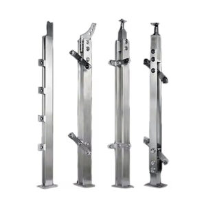
Bracket and post locations are a structural coordination problem before they are a hardware selection problem. The spacing and placement of supports along a run has to respond to the actual path geometry established earlier, including every turn, return, and change in elevation, because each of those features changes where a support can physically be placed and how much unsupported span the rail carries between supports. A run with frequent direction changes concentrates support requirements near those changes in a way a long straight run does not, and the bracket or post family chosen for one condition will not necessarily suit the other.
The core judgment here is matching the bracket or base to the substrate and finish build-up that has actually been verified at each support location, rather than to the substrate assumed on a drawing. A wall-mounted bracket depends on the wall construction behind the finish surface, and a post base depends on the floor, landing, or structural element it attaches to; where either of those conditions differs from what was assumed, the bracket or base selected against the assumption may not perform the way the selection intended, even though it looks correct against the drawing.
What stays outside the hardware selection decision is the structural adequacy of the connection itself. Confirming that a bracket or base is matched to the verified substrate is a selection and coordination task; confirming that the resulting connection carries the loads the installed assembly will see is a structural decision that belongs with the responsible project parties, not with the hardware specification alone. ASTM E985 covers basic design and performance criteria for permanent metal railing systems at a scope level, but the detail needed to evaluate a specific support condition sits behind that standard’s paywalled text, and no compliance with it can be assumed from the hardware alone. A project comparing wall-mounted and post-mounted approaches for a given run is choosing between two different support interface strategies, each with its own substrate verification and bracket-matching requirements, and the choice has consequences for how the supports are coordinated along the rest of the run.
Returns, terminations, corners, and transitions at adjoining runs
A return, a termination, and a transition to an adjoining run are three different geometric conditions, and each resolves differently depending on what the handrail connects to at that point. A return brings the gripping surface back to the adjacent wall, post, or surface so that the end of the rail does not project into the path of travel; a termination ends the run at a point where no adjoining run continues; a transition connects one run to another, whether that adjoining run continues at the same elevation, steps to a different elevation, or changes mounting approach entirely. Treating all three as the same detail risks a run that satisfies the requirement at some terminations but not at others.
Where a run terminates at an open end, the return detail has to account for the clearance and gripping-surface continuity established earlier in the run, carrying it through to a conclusion rather than stopping abruptly. Where a run transitions into an adjoining run, whether that adjoining run belongs to the same project scope or to a separate contract, the transition point is where two sets of component decisions meet, and the coordination has to confirm that gripping surface, clearance, and support spacing remain consistent across the join rather than changing abruptly at the boundary.
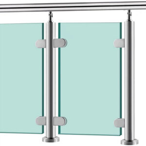
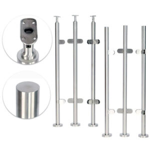
Corners introduce their own coordination requirement, because a corner changes the direction of the gripping surface without necessarily changing its elevation, and the bracket or post nearest the corner often has to accommodate a different load path and a different clearance relationship than a bracket on a straight segment. The resource comparing post-mounted and wall-mounted stainless steel handrail systems addresses how these mounting approaches differ at the system level, which bears directly on how a corner or transition is detailed depending on which mounting approach governs each side of the connection. The requirement to carry gripping surface, clearance, and extension provisions through these conditions still depends on the actual project coverage and the currently adopted requirements identified earlier, because a return or extension detail acceptable under one adopted basis may not satisfy another.
Material, finish, joints, tolerances, and site-measurement responsibilities
Material grade, finish, joint method, and dimensional tolerance are specification decisions that have to be fixed before fabrication, but each depends on conditions the project defines rather than on the hardware category alone. The material and finish suited to an interior fit-out run differ from those suited to a run exposed to an exterior or corrosive environment, and the finish build-up at each support location, already addressed as part of substrate verification, has to be consistent with the finish specified for the visible handrail components themselves. A mismatch between the specified finish and the environment the run will actually serve is a decision point that belongs to the project team defining the application, not an assumption the hardware order can resolve on its own.
Joint method and tolerance are connected in a way that is easy to underestimate. A continuous gripping surface relies on joints that do not interrupt the hand’s path, which means the tolerance allowed at each joint has to be tight enough to preserve that continuity across every return, transition, and change in elevation already established in the run’s geometry. Where a run includes a high number of turns and transitions, the number of joints increases accordingly, and the cumulative tolerance across those joints becomes a coordination question for the full run rather than a question answered joint by joint.
Site measurement is the step that reconciles the drawn geometry with as-built conditions, and it sits at the boundary between design intent and fabrication accuracy. Dimensions taken from drawings describe intended geometry; dimensions taken on site confirm what is actually there, including substrate position, finish build-up, and any deviation from the drawn layout accumulated during construction. Assigning responsibility for that site measurement, and confirming which party performs and verifies it, is necessary before fabrication proceeds, because a handrail fabricated to drawing dimensions without site verification carries the risk of every discrepancy between the drawing and the built condition. The submittal process documented in the resource on stainless steel handrail project submittals addresses how drawings, material certifications, load reports, and finish samples get assembled for project review, which is the documentation layer that follows once material, finish, joint, and tolerance decisions are fixed.
Release package covering drawings, samples, records, and inspection scope
| Package element | Project-specific content to include | Limite de decisão |
|---|---|---|
| Drawings | Path geometry, landings, turns, changes in elevation, support locations, returns, transitions, joints, and tolerances | Documents the coordinated package proposed for release; adopted requirements and actual substrate conditions still require project verification. |
| Samples | The material and finish sample required for the project | Provides the project reference for material and finish before release. |
| Records | The material, load, and other records required by the project | Defines the documentary scope; a record alone does not establish compliance or an acceptance result without the applicable project criteria. |
| Inspection scope | The checks, evidence, and acceptance criteria assigned by the project | Defines what the project will inspect; criteria and outcomes remain project-specific. |
The release package is where every decision made earlier in the project gets converted into documentation the project can review and act on before the handrail is released for fabrication or installation. Drawings carry the path geometry, landings, turns, changes in elevation, support locations, returns, transitions, joints, and tolerances established throughout the project, but a drawing documents the coordinated package being proposed; it does not by itself confirm that the adopted requirements or the actual substrate conditions match what the drawing assumes. That confirmation still depends on the project verification steps addressed earlier, and a drawing set that looks complete can still rest on an unverified assumption if that verification has not happened.
Samples serve a narrower purpose: they give the project a physical reference for the material and finish specified, so that approval happens against an actual sample rather than a written description alone. Records, whether material certifications, load reports, or other documentation the project requires, define what will be kept on file, but a record’s existence does not by itself establish that the installed assembly meets the applicable criteria; the record has to be matched against the specific criteria the project has adopted for it to carry that weight.
Inspection scope closes the package by defining what the project will actually check, against what evidence, and against what acceptance criteria. Where a project’s inspection scope differs from what the drawings, samples, and records anticipate, gaps can appear between what was documented and what gets verified in the field, which is why confirming the inspection scope as part of the release package, rather than after installation, keeps the documentation aligned with what the project will actually accept. Each element in this package, from ESANG’s role in supplying coordinated handrail components through to the project’s own acceptance process, depends on the project-specific information carried forward from every earlier decision in the run, and none of these elements substitutes for the others.
Perguntas frequentes
P: Why should component families be selected only after the full handrail route is mapped?
A: The travel path, landings, turns, terminations, and elevation changes determine where supports, returns, and transitions must be coordinated. Establish that geometry first so tube, bracket, and post-family choices respond to the actual run rather than an assumed layout.
P: How should a project divide wall-mounted and post-mounted portions of a handrail run?
A: Identify the mounting approach for each portion of the route and coordinate every change of interface. For each support condition, verify the substrate and finish build-up before selecting brackets or bases, while leaving structural connection decisions with the responsible project parties.
P: Which accessibility or code provisions should be applied to the handrail package?
A: Apply the provisions that match the project’s actual coverage and currently adopted requirements. Use those project-specific criteria to confirm gripping surface, clearance, continuity, and extension details rather than treating a general guide or specification structure as universal.
P: What should be resolved when one handrail run meets a corner, termination, or change in elevation?
A: Resolve the adjoining geometry as one coordinated condition, including the return or transition and its relationship to the gripping path, clearances, and supports. Show the agreed condition in the package drawings before release so it is not left to interpretation at the interface.
P: Do material or load records by themselves establish that a handrail package is compliant or accepted?
A: No. Include the records required by the project, but evaluate them against the applicable project criteria and assigned inspection scope. The project must still define what evidence will be checked and how acceptance will be determined.
P: What should be confirmed before releasing the handrail supply package?
A: Confirm that drawings capture the coordinated geometry, supports, returns, transitions, joints, and tolerances; that required material and finish samples are identified; and that required records and inspection criteria are assigned. Also make the site-measurement responsibilities explicit so the released information is tied to verified project conditions.