Freezing shop drawings before adapter geometry is confirmed is one of the more predictable sources of late-stage rework in glass railing projects. A wrong adapter that shifts the glass line by a few millimeters, or one that covers a hole pattern incorrectly, forces replacement fittings and resubmission — at a project stage where neither the schedule nor the budget has room for it. The geometry decisions that prevent this aren’t complex, but they require a specific sequence: post connection details and wall conditions confirmed before glass hole patterns are locked, not after. What follows gives specification teams, installers, and submittal reviewers a clearer basis for approving or flagging brackets before the drawings are committed.
Adapter schedules control the glass-to-structure interface
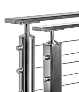
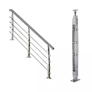
An adapter schedule does something a component list alone cannot: it maps each bracket or adapter to the specific structural condition it connects — post type, wall construction, glass hole pattern, edge clearance, and surface finish — so that mismatches surface on paper rather than during installation. Without that schedule, each interface gets resolved informally, which means the decisions are being made, just at the wrong project stage and by people who don’t always have the full picture.
The schedule itself is a coordination instrument. It doesn’t replace structural review or glass fabrication drawings, but it forces the questions that prevent late incompatibilities: Does this post connection allow the adapter to seat correctly at the planned glass line? Does the wall condition support the bracket type selected? Is the specified finish consistent across hardware at this elevation? These questions are easier to answer at the schedule stage than after glass has been ordered to a hole pattern that assumes an adapter geometry nobody has confirmed.
Where ASTM E894-88(2004) is referenced as a testing framework for permanent metal railing anchorage, the practical implication for adapter schedules is the same: anchorage conditions need to be defined early enough that the adapter geometry can be verified against them, not assumed. The schedule is the mechanism that makes that verification possible before shop drawings are submitted for approval.
Post, wall and glass hole pattern coordination
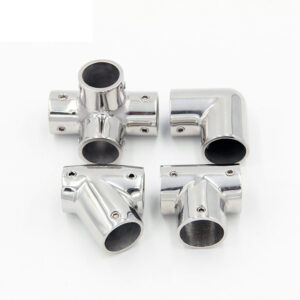
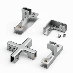
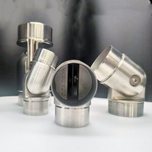
Bracket type selection and hole pattern layout are not independent decisions. The bracket geometry determines whether a glass hole is needed at all, where it must land relative to the bracket seat, and how much clearance the surrounding structure must provide. Getting the sequence wrong — fixing the glass hole pattern before the bracket type is confirmed — creates a mismatch that often isn’t visible until fabrication is complete.
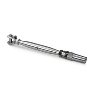
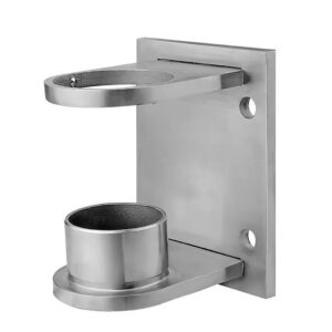
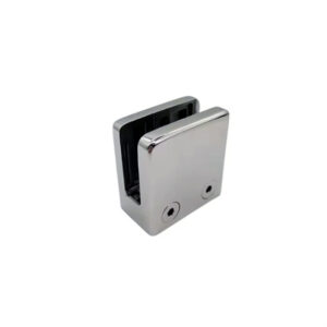
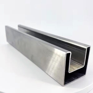
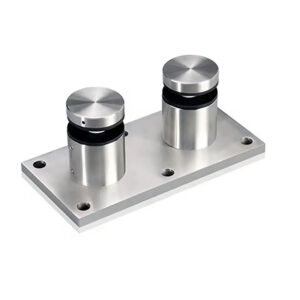
Slip-over clamps and ceiling support bars are worth noting here precisely because they eliminate the hole pattern problem entirely. No holes mean no drilling error, no hole position tolerance, and no coordination between glass fabricator and hardware supplier on hole location. For projects where the wall or post condition is still being resolved, specifying a bracket type that avoids glass penetration removes one variable from an already-compressed timeline.
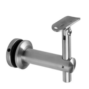
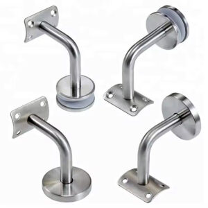
Where holes are required, the structural interface imposes hard geometric constraints. A 90-degree wall bracket, for example, requires at least 26 mm between the bracket seat and the edge of the glass hole. This is a design figure from product geometry, not a codified universal rule, but the consequence of ignoring it is practical: the bracket won’t seat correctly, and the shop drawing will reflect a geometry that can’t be built as drawn. When wall thickness or projection doesn’t provide that clearance, the correct response is to substitute a U-bracket or 180-degree bracket before drawings are submitted — not after. For wider panels, the coordination requirement extends further: glass panels beyond 1200 mm typically need a support bar for the return panel, which adds a layout constraint that must align with the post or wall interface before that zone of the drawings can be considered resolved.
| Critério | Requisito | Implicações |
|---|---|---|
| Bracket types requiring no glass holes | Slip‑over clamps, ceiling support bar | Eliminates hole misalignment and drilling error risk; no hole pattern coordination needed. |
| Minimum distance for 90° wall bracket | At least 26 mm from glass hole | If wall thickness is less than 26 mm, bracket placement fails; use a U‑bracket or 180° bracket to avoid rejection. |
| Glass panel width and support bar | Panels wider than 1200 mm need a support bar for the return panel | Adds a structural coordination requirement; support bar layout must align with post/wall interface to secure the panel. |
The structural consequence of skipping this coordination isn’t abstract. A hole pattern locked to a bracket type that was later changed, or a bracket placement that assumes wall clearance that doesn’t exist, produces shop drawings that can’t survive a competent geometry check. Catching either condition before submittal is a matter of sequencing the coordination correctly.
Adjustable versus fixed bracket tradeoffs
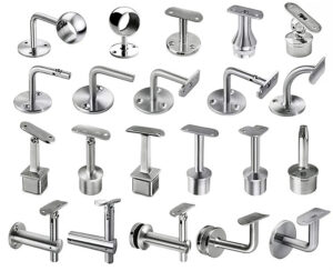
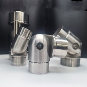
The choice between adjustable and fixed brackets carries a tradeoff that teams tend to underestimate during specification: adjustable brackets absorb field tolerance, but they do so by adding parts, adjustment mechanisms, and inspection points. Fixed brackets are simpler and cleaner, but they transfer all the tolerance burden back onto the geometry of the glass holes, the wall surface, and the post connection.
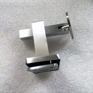
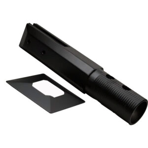
Adjustable wall mount clamps — those that accommodate non-standard angles and use cover plates to conceal screw heads — are useful where the structure doesn’t present a consistent, predictable surface condition. They buy margin. That margin has a cost: each adjustment point is also an inspection point, meaning the review process for an adjustable bracket installation is more involved than for a fixed one. If that inspection overhead isn’t accounted for in the submittal timeline, it becomes a problem.
Fixed brackets, by contrast, have no adjustment points to verify. Standard 90-degree or 180-degree clamps seat correctly or they don’t, and the check is straightforward. The exposure is that any assumption about geometry that turns out to be wrong — wall flatness, post alignment, hole position — shows up as a mismatch with no recovery option short of reordering hardware. Projects where the structure is well-controlled and the glass fabrication is being coordinated closely with the hardware schedule can carry that exposure without difficulty. Projects where field conditions are still variable at the time of hardware specification should treat adjustable brackets not as a preference but as a risk management decision.
| Tipo de suporte | Tolerance Accommodation | Complexity & Inspection | Geometry Risk if Misaligned |
|---|---|---|---|
| Adjustable (e.g., CRL Altea series) | Accepts non‑standard angles; cover plates hide screw heads | Adds adjustment points and inspection steps to verify correct alignment | Can absorb some field tolerance, but adjustment mechanisms introduce potential failure points |
| Fixed (standard 90° or 180° clamps) | No adjustment; demands precise geometry alignment | Simple mounting, fewer inspection points | Any misalignment in glass holes or wall placement can cause the bracket not to fit, leading to rejection |
The decision point is not which bracket type is generically better. It’s which type fits the level of geometric certainty available at the time the hardware is being specified — and whether the project can absorb the inspection overhead that adjustable brackets require, or the geometric precision that fixed brackets demand.
Shop drawing rejection risks from mismatched geometry
Most shop drawing rejections tied to bracket geometry trace back to one of two failure patterns: a bracket placed too close to a glass hole for its geometry to function correctly, or a bracket missing the edge protection needed to prevent metal-to-glass contact.
The 26 mm clearance figure reappears here not as a new threshold but as the same design constraint from hole pattern coordination, now acting as a rejection mechanism. A 90-degree wall bracket specified where wall geometry puts the hole edge closer than 26 mm isn’t a borderline case — the bracket physically cannot seat as drawn. When that condition survives into a submitted shop drawing, the reviewer has no option but to reject it. The fix requires either a bracket substitution or a redesign of the wall detail, and either path takes time that wasn’t in the schedule.
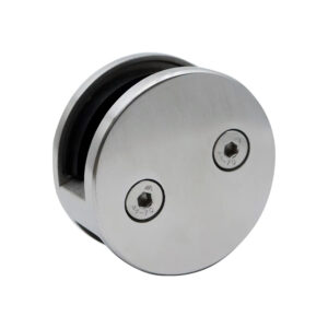
Missing nylon or rubber spacers inside brackets and clamps is a quieter failure, but potentially more consequential. Metal-to-glass contact doesn’t always surface during submittal review — it can pass unnoticed if the drawing shows the correct bracket profile but doesn’t specify the protection material explicitly. The result may be scratching or glass damage that appears during installation or, worse, during service. By that point, the gap in the original specification has compounded into a warranty or replacement claim.
| Check Item | Mismatch Condition | Rejection Consequence |
|---|---|---|
| 90° wall bracket placement relative to glass hole | Distance from hole edge is less than 26 mm | Bracket unfit; shop drawings rejected or requiring rework |
| Bracket edge protection (Nylon spacers) | Nylon spacers missing or omitted | Metal‑to‑glass contact causes scratching or glass damage, leading to rejection |
Both conditions are avoidable if the bracket schedule is specific enough. A schedule that lists bracket type, hole edge clearance, and spacer material for each connection leaves the reviewer with a clear basis for confirmation. One that lists only bracket model numbers leaves the geometry questions open, and those open questions tend to resolve themselves at the worst possible time.
For projects involving glass panel support brackets across multiple wall or post conditions, the schedule needs to account for each condition separately — a single bracket spec applied uniformly across variable geometry is how both of these failure patterns get introduced.
Final overlay check before bracket approval
Bracket approval should not precede a direct overlay of the adapter drawings against the glass hole schedule and the post or wall interface drawings. This isn’t a formal inspection protocol from a named standard; it’s a practical verification step that closes the gap between what was specified and what the fabricated components will actually require.
The overlay check has a specific scope. It confirms that the adapter geometry seats correctly at each connection point — that the post-to-glass adapter aligns with the post profile, that the wall bracket clears the hole edge at the correct distance, and that the glass line produced by the assembled hardware matches the intended face. It also confirms that rubber or nylon protection is called out inside every bracket and hinge where glass contact occurs. A drawing set that shows the correct bracket type but omits the spacer specification is not complete, and approving it as complete transfers the risk forward.
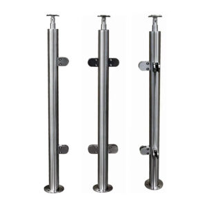
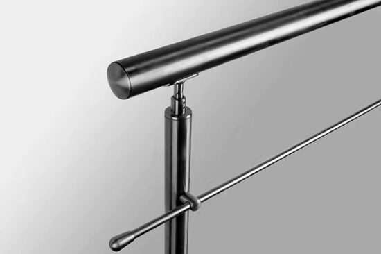
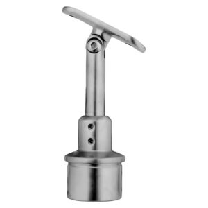
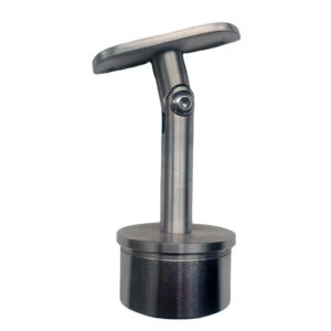
Where post-to-glass connections are part of the assembly — particularly at corners or intermediate posts — post to glass adapters should be reviewed against both the post section geometry and the glass hole schedule simultaneously. An adapter that fits the post but doesn’t align with the hole pattern as fabricated produces the same outcome as a wrong bracket: a component that can’t be installed as drawn. Confirming both interfaces at the overlay stage is faster than managing the substitution after approval.
The overlay check is also where decisions about adjustable versus fixed brackets get their final validation. An adjustable bracket approved without confirming its range of motion against the actual wall condition may reach the field and still require shimming or repositioning that the drawing didn’t account for. Confirming adjustment range against the verified geometry before approval converts the bracket selection from an assumption into a confirmed fit.
The practical sequence that prevents late-stage rework is straightforward, even if following it requires some upstream discipline: confirm post type, wall condition, and bracket geometry before the glass hole pattern is locked; verify edge clearances and spacer specifications before submittal; and run the overlay check before bracket approval is issued. Each of those steps is cheaper to complete before drawings are frozen than after.
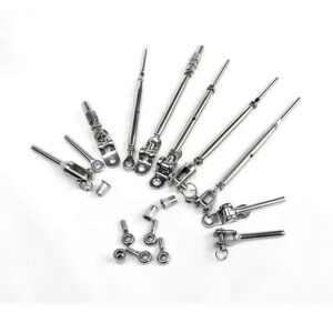
For teams managing projects with multiple wall or post conditions — or where the structure isn’t fully confirmed at the time hardware is being selected — a detailed adapter schedule is the most reliable way to keep bracket geometry decisions visible and reviewable. The glass mounting adapters used at each interface need to appear in that schedule with enough specificity — hole edge clearance, bracket type, protection material, finish — that any mismatch can be caught on paper rather than in the field. That level of schedule detail is what makes bracket approval a confirmation rather than a risk.
Perguntas frequentes
Q: What happens if the wall thickness is confirmed only after glass has already been ordered to a hole pattern?
A: The hole pattern will likely need to be scrapped and glass reordered. Once a hole pattern is fabricated to a specific bracket geometry — such as a 90-degree wall bracket requiring at least 26 mm from hole edge to bracket seat — changing the bracket type to suit a thinner wall means the existing holes land in the wrong position for the substitute bracket. There is no field adjustment that recovers a misplaced glass hole. The only way to avoid this outcome is to confirm wall thickness and bracket type before releasing glass to fabrication.
Q: After the overlay check is complete and bracket approval is issued, what should the next coordination step be?
A: The next step is transmitting the confirmed bracket and adapter schedule to the glass fabricator with explicit hold points flagged — specifically hole position tolerances, edge clearances, and any spacer or protection material requirements tied to each connection. Approval without that transmission leaves the fabricator working from incomplete information, and discrepancies between the approved bracket geometry and the fabricated hole pattern are typically only caught during installation, not before.
Q: Does the 26 mm hole-edge clearance threshold apply to all bracket types, or only to 90-degree wall brackets?
A: It applies specifically to 90-degree wall bracket geometry. Bracket types that don’t require glass penetration — such as slip-over clamps or ceiling support bars — have no equivalent threshold because there is no hole to clear. U-brackets and 180-degree brackets carry their own seating geometry and may impose different clearance requirements. Applying the 26 mm figure uniformly across bracket types would be incorrect; the constraint is product-geometry specific and must be checked against the actual bracket being specified at each connection.
Q: When is specifying adjustable brackets the wrong choice even on a project with variable field conditions?
A: When the submittal and inspection timeline cannot accommodate the additional review overhead they require. Adjustable brackets absorb geometric tolerance, but each adjustment point is also an inspection point — confirming that the bracket has been set correctly within its range of motion adds steps to field verification that fixed brackets don’t require. On projects with compressed schedules or limited inspection capacity after hardware is installed, that overhead can create delays or unchecked conditions that offset the tolerance benefit entirely. Variable field conditions make adjustable brackets attractive; a schedule that can’t support their inspection requirements makes them a liability.
Q: Is a detailed adapter schedule necessary if a project uses only one bracket type throughout?
A: Yes, because the schedule’s function isn’t to manage bracket variety — it’s to document the verified interface conditions at each connection. Even with a single bracket type, wall conditions, post profiles, glass hole positions, and edge clearances can vary across elevations. A schedule that records the confirmed geometry at each connection gives the submittal reviewer a basis for approval and creates a reference if field conditions deviate from what was drawn. Without it, uniform bracket specification across variable geometry is an assumption, and that assumption is where mismatches enter drawings undetected.