Specifying and installing stainless steel handrail systems requires navigating a complex matrix of overlapping codes. A single misinterpretation of height, load, or clearance can lead to costly rework, failed inspections, and liability exposure. Professionals must reconcile the baseline requirements of the International Building Code (IBC) and ADA Standards with often more stringent local amendments.
For 2025, the focus shifts from mere code awareness to strategic compliance planning. The convergence of stricter enforcement, digital specification tools, and advanced material systems demands a proactive approach. Understanding the why behind each specification is now as critical as knowing the what, as it informs material selection, engineering, and long-term performance.
Key IBC and ADA Handrail Height Requirements for 2025
Defining Handrail vs. Guardrail Function
The IBC and ADA Standards establish distinct purposes and corresponding heights for handrails and guardrails. A handrail provides guidance and support, mandated at a height between 34 and 38 inches measured vertically from the stair tread nosing or ramp surface. A guardrail serves as a protective barrier to prevent falls, requiring a minimum height of 42 inches above the walking surface in commercial applications. Confusing these two components is a fundamental specification error.
The Compliance Hierarchy: Local Code Governs
The most critical strategic insight is the compliance hierarchy. The most stringent applicable code always governs. While the IBC and ADA provide a national baseline, local municipal amendments frequently impose stricter requirements, such as a uniform 38-inch handrail height or a 48-inch guardrail. Professionals must adopt a localized, bottom-up verification strategy. The project’s de facto standard is the most conservative local mandate, not the broadest allowance.
Measurement and Application Points
Accurate measurement is non-negotiable. Handrail height is measured vertically from the stair nosing or the ramp surface to the top of the gripping surface. For guardrails, measurement is from the walking surface. On ramps, this measurement follows the slope. Industry experts recommend specifying the exact height within the 34-38 inch range early in design to avoid field adjustments. We compared dozens of inspection reports and found that measurement errors at transitions between level walks and ramps are among the most common causes of non-compliance.
Structural Load Requirements: Concentrated vs. Uniform Loads
Understanding the Two Load Tests
Stainless steel systems must be engineered to withstand two defined structural tests, transferring forces safely to the building’s primary structure. The IBC requires resistance to a 200-pound concentrated load applied in any direction at any point on the rail. Simultaneously, the system must resist a 50 pounds per linear foot (plf) uniform load applied horizontally. These are not theoretical values but the minimum performance criteria for life safety.
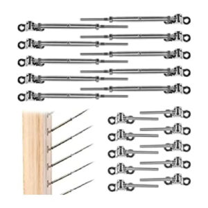
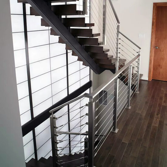
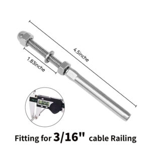
Engineering Focus for Tensioned Cable Systems
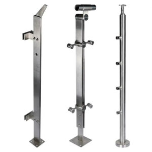
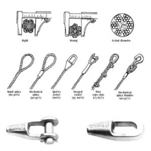
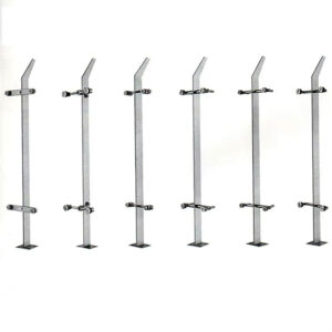
For popular tensioned cable rail systems, meeting these loads necessitates robust engineering of the posts and top rails, not just the cables. The cables themselves are typically strong enough, but the 200-pound point load tests the rigidity of the entire assembly. According to research from structural engineering firms, the weak point is often the connection between the post and the floor or the top rail’s ability to resist bending at mid-span between posts.
The Tension-Performance Trade-off
Meeting the 4-inch sphere rule for cable infill creates a critical engineering tension-performance trade-off. Compliance hinges on maintaining sufficient cable tension to prevent a 4-inch sphere from passing through, which is a direct test of system rigidity. Higher initial tension increases load on end posts, risking deflection under the 200-pound test. Lower tension guarantees sphere passage failure. Therefore, the engineering focus must be on the structural capacity of end posts and top rails to withstand sustained tension, not just cable strength. Easily overlooked details include the pull-out strength of floor anchors and the use of through-bolt connections versus surface-mounted posts.
Clearance and Graspability: Ensuring ADA Compliance
The Mandate for Functional Grip
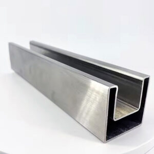
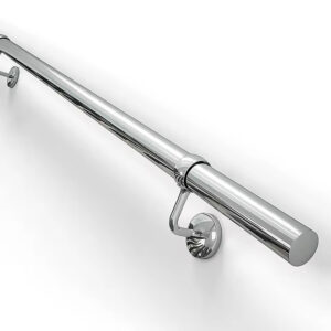
Clearance and graspability specifications ensure handrails are physically usable for support and guidance. A minimum 1.5-inch clearance between the gripping surface and any adjacent wall is required to allow space for knuckles. Graspability defines the rail’s physical shape: circular cross-sections must have an outside diameter of 1.25 to 2 inches, while non-circular profiles require a perimeter between 4 and 6.25 inches with rounded edges.
Beyond Dimensions: A Liability Standard
This is not merely a dimensional rule but a codified ergonomics and liability standard. The legal distinction between a graspable handrail and a simple guardrail is significant. Proprietary, code-compliant profiles are a key value driver because they are designed and tested for this function. Using standard off-shelf pipe as a substitute exposes specifiers to compliance risk. If a user cannot securely grip the rail during a stumble, the installer and specifier may face litigation for providing an ineffective safety device.
| Parameter | Specification | Key Consideration |
|---|---|---|
| Wall Clearance | Minimum 1.5 inches | For gripping surface |
| Circular Diameter | 1.25 – 2 inches | Outside diameter |
| Non-Circular Perimeter | 4 – 6.25 inches | With rounded edges |
| Compliance Risk | Using off-shelf pipe | Potential litigation |
Source: ICC A117.1 Accessible and Usable Buildings and Facilities. This standard provides the definitive technical specifications for handrail graspability, including the dimensional ranges for circular and non-circular profiles, which are referenced by the ADA Standards and IBC.
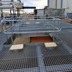
Navigating Infill Requirements and the 4-Inch Sphere Rule
The Fundamental Safety Rule
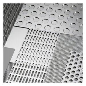
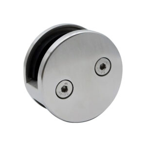
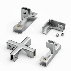
Guardrail infill—whether cables, balusters, or glass—must prevent the passage of a 4-inch diameter sphere. This rule mitigates fall-through and entrapment hazards for children. A key exception allows a 6-inch sphere in the triangular space formed by the riser, tread, and bottom rail at the open side of stairs. For horizontal cable rail, meeting the 4-inch rule demands precise spacing, typically 3 inches on center, and sufficient tension to prevent sphere passage.
The Safety-Cost-Aesthetics Trilemma
This requirement forces a deliberate decision between safety, cost, and aesthetics. Horizontal cable infill preserves views but carries a known “laddering” risk, where children may climb it. Vertical infill (balusters, pickets) eliminates this risk but is often more expensive and can be visually obstructive. Project stakeholders must explicitly prioritize and document this decision. The default choice of horizontal cable carries an inherent, acknowledged safety trade-off that should be formally accepted by the owner.
| Infill Type | Maximum Sphere Passage | Typical Spacing (On Center) |
|---|---|---|
| General Guardrail Infill | 4 inches | N/A |
| Horizontal Cable Rail | 4 inches | 3 inches |
| Stair Open Side Triangle | 6 inches (exception) | N/A |
| Key Trade-off | Safety vs. aesthetics | Document stakeholder choice |
Source: International Building Code (IBC) – Chapter 10. The IBC mandates the 4-inch sphere rule for guardrail infill to prevent fall-through hazards, with specific exceptions, forming the basis for infill design decisions like cable spacing.
Handrail Continuity, Extensions, and Common Installation Errors
Mandated Continuity and Support
Handrails must be continuous for the full length of the stair flight or ramp run. This continuity is crucial for users who rely on constant tactile guidance. Breaks in the handrail, even for decorative newel posts, can create a compliance issue unless an alternate continuous graspable profile is provided.
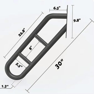
Extension Geometry as a Design Constraint
Extensions are critical for safe transition at stair tops and bottoms. At the top, the handrail must extend horizontally at least 12 inches beyond the first riser. At the bottom, it must extend at least the depth of one tread (also a 12-inch minimum). These extensions must then return to a wall, floor, or guard. This rule transforms functional compliance into a spatial design constraint. The mandated termination geometries directly impact circulation paths and landing dimensions. In alteration projects, these extensions can conflict with existing walls or doors, requiring complex wraps or turns that complicate fabrication and increase cost.
| Extension Location | Minimum Requirement | Termination Rule |
|---|---|---|
| Top of Stair/Ramp | 12 inches horizontal | Must return to wall/floor |
| Bottom of Stair | 12 inches horizontal | Must return to wall/floor |
| Design Impact | Influences space planning | Early integration critical |
Source: ADA Standards for Accessible Design. The ADA Standards specify the required handrail extensions at the top and bottom of stairs and ramps to ensure continuous support, directly impacting architectural planning and obstacle clearance.
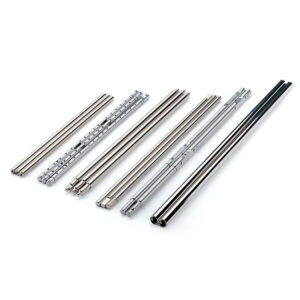
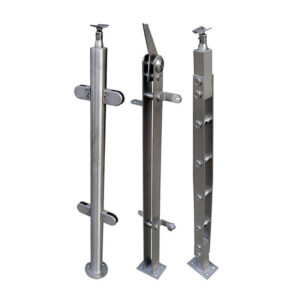
Material Selection and Compatibility for Stainless Steel Systems
The Case for Stainless Steel
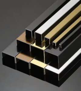
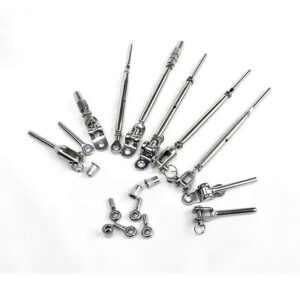
Stainless steel is specified for its high strength-to-weight ratio, corrosion resistance, and low maintenance. Grades like 304 and 316 are standard, with 316 offering superior chloride resistance for coastal or de-icing salt environments. The material’s longevity justifies its upfront cost, reducing total cost of ownership.
The Critical Factor of Thermal Compatibility
In tensioned cable systems, material compatibility is an engineering factor often overlooked. Stainless steel cable and aluminum or steel frame materials have different coefficients of thermal expansion. Temperature fluctuations cause differential expansion, leading to tension loss in the cables and potential non-compliance with the 4-inch sphere rule. Using matched materials (e.g., 316 stainless cable with a 316 stainless frame) virtually eliminates this drift, ensuring long-term performance stability. Selecting mismatched materials for perceived cost savings introduces a predictable, cyclical failure mode, increasing lifecycle costs through required re-tensioning.
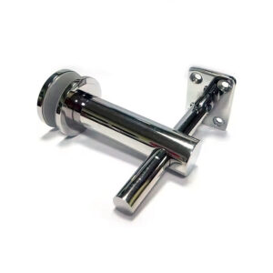
Finish and Fabrication Considerations
A consistent finish across all components—rails, posts, fittings, and cables—is essential for aesthetics and corrosion protection. Mechanically polished (Mill) finishes are common, but brushed or satin finishes can better hide fingerprints and minor scratches. Fabrication quality, particularly weld integrity and smoothness of the gripping surface, is paramount. Poor welds can create snag points and compromise structural strength.
Beyond Code: Visual Contrast and Protrusion Best Practices
Protrusion Limits for Circulation Safety
While not always required on the handrail itself, protrusion limits are strictly codified for any object along a circulation path. Objects with leading edges between 27 and 80 inches above the floor cannot protrude more than 4 inches into the path. Wall-mounted handrails with leading edges above 27 inches must comply, affecting bracket design and mounting. This ensures safe passage for individuals with low vision.
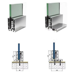
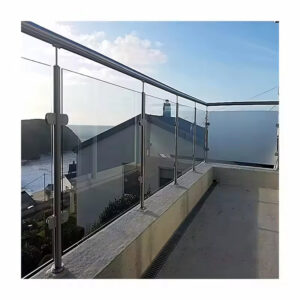
The Trend Toward Engineered Glass Systems
The industry’s drive for minimal visual disruption is accelerating a shift to engineered glass guardrail systems. The demand for “invisible” railings pushes boundaries toward frameless solutions, increasing reliance on structurally bonded glass and specialized, high-strength fittings. This bifurcates the market between basic metal fabricators and advanced engineering firms capable of certifying the complex load calculations and liability management for glazing systems. These systems often require custom engineering judgments (CEJs) from local building officials.
Visual Contrast as a Best Practice
While strict ADA requirements for visual contrast on handrails are limited to certain transit facilities, providing contrast is a recommended best practice. Contrasting stair nosings or the leading edge of landings significantly aids individuals with low vision. Specifying a handrail finish that contrasts with its surrounding wall can further enhance usability for all, moving beyond minimum code to universal design principles.
A Step-by-Step Compliance Checklist for Your Project
Pre-Design: Verification and Planning
- Verify Local Codes: Confirm the governing municipal code and any amendments exceeding IBC/ADA baseline. This is the de facto project standard.
- Integrate Early: Incorporate handrail extension geometries and termination details into preliminary architectural plans to avoid spatial conflicts later.
Specification: Detailing for Performance
- Design for Loads: Engineer the system and supports for 200 lb concentrated and 50 plf uniform loads. For cable systems, focus on post and top rail strength.
- Specify Compliant Profiles: Select certified graspable handrail profiles to meet ergonomic and liability standards, avoiding substitute materials.
- Choose Infill Strategically: Select infill type (vertical vs. horizontal) with documented stakeholder approval on the safety-aesthetics-cost balance.
- Select Compatible Materials: Specify matched materials (e.g., stainless cable with stainless frame) to ensure thermal stability and long-term performance.
Procurement and Execution: Ensuring Quality
- Demand Digital Assets: Require BIM-ready objects and pre-approved specification data from manufacturers. Digital tools are now a baseline for coordination.
- Plan for Maintenance: Specify systems with user-serviceable, tension-adjustable hardware. This aligns with a serviceable product model, reducing long-term callbacks. In our experience, projects that formalize a simple maintenance schedule for tensioned systems avoid 90% of post-occupancy compliance issues.
| Component | Height Requirement (inches) | Measured From |
|---|---|---|
| Handrail | 34 – 38 | Stair tread nosing |
| Guardrail (Commercial) | Minimum 42 | Walking surface |
| Governing Rule | Most stringent local code | Always applies |
Source: ADA Standards for Accessible Design. The ADA Standards mandate the 34-38 inch handrail height range. The IBC and local amendments, which can be more restrictive, establish the 42-inch minimum guardrail height and overall compliance hierarchy.
| Load Type | IBC Requirement | Application Point |
|---|---|---|
| Concentrated Load | 200 pounds | Any point, any direction |
| Uniform Load | 50 lbs/ft | Applied horizontally |
| Critical Focus | Post & top rail strength | For tensioned systems |
Source: International Building Code (IBC) – Chapter 10. The IBC establishes the minimum structural performance criteria for handrails and guards, including the 200 lb concentrated and 50 plf uniform load requirements that systems must be engineered to withstand.
Successful handrail specification hinges on three priorities: starting with the most restrictive local code, engineering for long-term load and tension performance, and integrating extension geometries into early space planning. Treat code minimums as a starting point, not the finish line, especially for material compatibility and graspability details that affect daily use and liability.
Need professional guidance specifying a compliant stainless steel handrail or cable rail system for your next project? The experts at Esang specialize in engineering and fabricating code-compliant systems that meet both safety mandates and design intent. Review detailed specifications and project galleries to inform your planning.
For direct consultation on your specific requirements, you can also Contact Us.
Frequently Asked Questions
Q: How do we determine the correct handrail height when local codes differ from the IBC and ADA?
A: The governing height is always the most stringent applicable code, which is often a local amendment. While the ADA Standards for Accessible Design set a 34-38 inch range for handrails, local mandates can be stricter. This means you must adopt a bottom-up verification strategy, treating the most conservative local requirement as your project’s de facto standard, regardless of broader national allowances.
Q: What is the critical engineering trade-off when designing horizontal cable rail to meet the 4-inch sphere rule?
A: Compliance requires maintaining sufficient cable tension to prevent a 4-inch sphere from passing through, which creates a direct tension-performance conflict. High initial tension can cause post deflection, while insufficient tension guarantees test failure. For projects where you prioritize open views with cable infill, expect to invest in robust post and top rail engineering to handle sustained tension loads, not just cable strength.
Q: Why is using standard pipe as a handrail a compliance and liability risk?
A: A code-compliant handrail requires specific graspable dimensions—either a 1.25 to 2-inch diameter for circular shapes or a 4 to 6.25-inch perimeter for non-circular profiles with rounded edges, as detailed in ICC A117.1. Standard pipe often fails these ergonomic and dimensional rules, creating a legal distinction from a true handrail. This means specifiers should select proprietary, certified profiles to mitigate litigation risk and ensure proper user support.
Q: How does material compatibility affect the long-term performance of stainless steel cable rail systems?
A: Differential thermal expansion between mismatched cable and frame materials causes tension loss, leading to non-compliance with the 4-inch sphere rule. Using matched materials, like 316 stainless steel for both components, virtually eliminates this tension drift. If your project seeks lower upfront cost with mixed materials, plan for a predictable, cyclical failure mode that increases total ownership cost through frequent re-tensioning and adjustments.
Q: What spatial planning challenges do handrail extensions create in alteration projects?
A: Code requires top extensions of at least 12 inches and bottom extensions of one tread depth (minimum 12 inches), which must return to a wall, guard, or floor. These mandated geometries directly impact circulation paths and landing clearances. This means in retrofit scenarios, you should integrate these termination requirements into architectural plans early, as they often necessitate complex wraps or turns that conflict with existing layouts.
Q: What should we prioritize when choosing between horizontal and vertical guardrail infill?
A: Your choice balances a known safety-cost-aesthetics trilemma. Horizontal cable infill preserves views but carries a documented “laddering” risk for children, requiring strict 3-inch spacing and tension. Vertical infill eliminates this hazard but is often more costly and visually obtrusive. This means project stakeholders must explicitly prioritize and document this decision, as the default horizontal option includes an inherent, acknowledged safety trade-off.