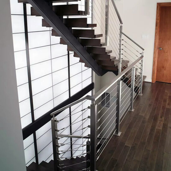
Installing a cable railing system presents a unique structural challenge. The project’s success hinges on a series of precise technical decisions, from post spacing to tensioning, that directly impact safety and longevity. A common misconception is that these systems are simple to install, but overlooking core engineering principles leads to excessive deflection, failed inspections, and costly callbacks.
For contractors and skilled DIYers, mastering these details is non-negotiable. Building codes mandate strict parameters, and the market now offers diverse fitting systems that segment installation approaches. Understanding the interplay between spacing, tension, and compliance transforms a complex assembly into a reliable, long-lasting guardrail.
Post Spacing and Mounting: Core Principles for Stability
Defining the Structural Framework
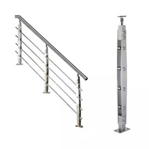
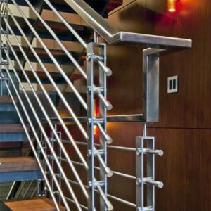
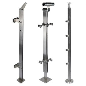
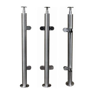
The post is the anchor point for all cable loads. Its spacing and mounting method are the primary determinants of system rigidity. Post spacing creates a direct trade-off between material cost and structural performance. Insufficient support leads to visible cable bowing and handrail sag, compromising both safety and aesthetics.
Application and Load Path
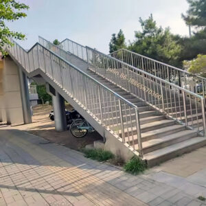
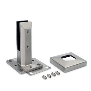
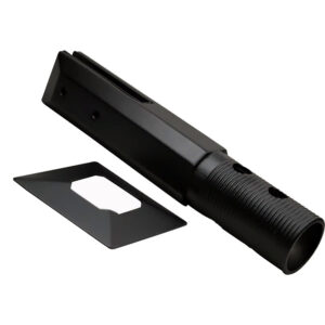
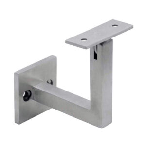
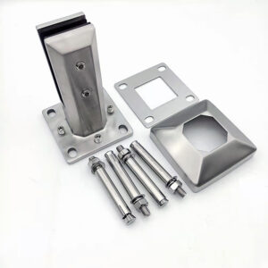
Every post must transfer tension loads back to the building’s solid framing. This requires precise mounting, whether surface-mounted to reinforced deck blocking, attached via fascia brackets, or core-drilled into concrete. Each post must be individually plumbed and leveled before final fastening; misalignment here compounds through every subsequent step, affecting hole alignment and cable run.
Impact of Incorrect Spacing
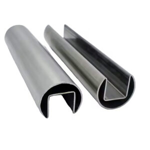
Exceeding maximum spans is a leading cause of system failure. The handrail and the cables have different support requirements. For cable support, intermediate posts or spacers are critical to control lateral movement. For the handrail itself, a longer span may be acceptable, but it must resist downward force and sag.
The following table clarifies the maximum spans for key components:
Maximum Spans for Structural Integrity
| Component | Maximum Span | Key Purpose |
|---|---|---|
| Cable Support | 4 – 4.5 feet | Controls lateral bowing |
| Handrail Support | 8 feet | Prevents sagging |
| Mounting Method | N/A | Transfers load to framing |
Source: Technical documentation and industry specifications.
In my experience, the single most common field error I see is underestimating the lateral load on intermediate posts, leading to a visibly wavy cable run that no amount of tensioning can correct.
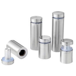
Cable Termination and Tensioning Methods Explained
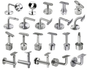
The Fitting Selection Problem
Securing cable ends involves choosing from a specialized array of fittings. This diversity solves adaptability issues but creates a significant selection bottleneck for installers. The choice fundamentally dictates the required tools, installation workflow, and future maintenance capability.
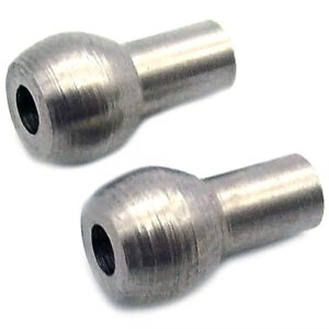
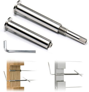
Swage vs. Swageless Systems
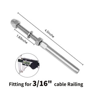
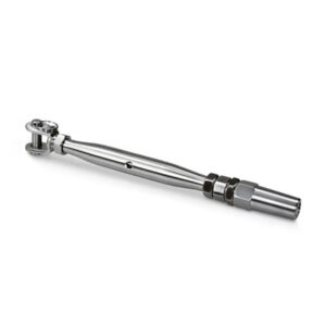
The two primary categories are permanent swage fittings and field-adjustable swageless systems. Swage fittings require a hydraulic or manual crimping tool to deform a sleeve around the cable, creating a permanent, high-strength connection. Swageless fittings, such as Push-Lock or Pull-Lock types, use internal wedges tightened with a standard Allen wrench. This allows for adjustment and even re-use of the cable.
Strategic Market Implications
This technical evolution directly influences market segments. Manufacturers promoting “no-swage” or tool-minimized kits are capturing the growing DIY and pro-amateur markets by reducing complexity and upfront tool investment. For professionals, the decision often centers on bulk material cost versus labor efficiency. The strategic shift is clear: simplicity and adaptability are winning over pure brute-strength permanence in many applications.
Step-by-Step Cable Tensioning Procedure and Sequence
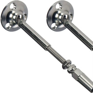
Initial Termination and Measurement
Begin by permanently fixing the cable at the “dead” end post. Run the cable to the tensioning end, pull it hand-taut, and mark the cut point. It is critical to add a pull-length allowance—typically 1 to 1.25 inches—to the measurement before cutting. This accounts for the portion of the cable that will be drawn into the fitting during final tensioning. Failure to add this length is a frequent, project-halting mistake.
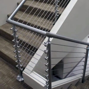
The Critical Tensioning Sequence
After terminating the cut end, apply final tension. The sequence of tensioning is as vital as the tension value itself. Always start with the middle cable in the run. Then, move to the cables immediately above and below it, alternating from one side of the middle to the other to balance the load on the post. Continue working outward to the top and bottom cables. This prescribed middle-out, alternating method prevents post warping and ensures even load distribution.
Validating Proper Tension
Proper tension is achieved when lateral deflection at the midpoint of a span is less than 1 inch under moderate hand pressure. Use a tension gauge if specified by the manufacturer or for critical applications. Avoid the temptation to over-tension; excessive force places undue stress on posts, fittings, and mounting hardware, potentially compromising the entire structure’s integrity.
Essential Building Code Compliance for Cable Railings
The Non-Negotiable Rules
Compliance with building codes is the ultimate constraint, with local amendments often representing the greatest project risk. Two universal rules govern design. First, the 4-Inch Sphere Rule mandates that a 4-inch sphere cannot pass through any opening in the guardrail infill. Second, guardrail height for residential decks is typically set between 36 and 42 inches, measured to the top of the handrail.
Industry Standards and Local Interpretation
The 4-inch rule has led the industry to adopt a standard maximum vertical cable spacing of 3 to 3 ⅛ inches. This provides a clear compliance buffer. However, successful contractors differentiate themselves by mastering local code relationships and permitting processes. They add value by navigating unique jurisdictional amendments, a service layer that prevents failed inspections and project delays.
The following table outlines key code parameters:
Key Building Code Parameters for Cable Railings
| Code Parameter | Required Specification | Industry Standard |
|---|---|---|
| Maximum Opening | 4-inch sphere cannot pass | 3 – 3 ⅛ inches |
| Guardrail Height (Residential) | 36 – 42 inches | 36 inches minimum |
| Load Capacity | Varies by jurisdiction | 200 lbs. lateral force |
Source: ICC A117.1 Accessible and Usable Buildings and Facilities. This standard establishes critical safety parameters for guardrails, including the 4-inch sphere rule for openings and minimum height requirements, which directly dictate cable spacing and system design.
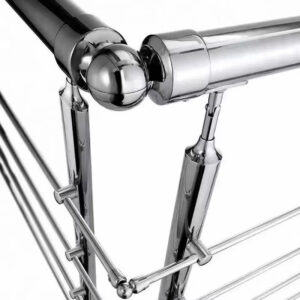
Technical Considerations for Stairs and Corners
Solving Geometric Complexity
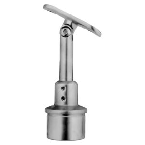
Stairs and outside corners introduce multi-plane geometry that demands precise planning. On stairs, cable spacing must be maintained parallel to the stair’s angle of descent. This requires angled terminal fittings matched to the stair pitch and careful calculation of cable pull-lengths, which are longer than the horizontal run due to the slope.
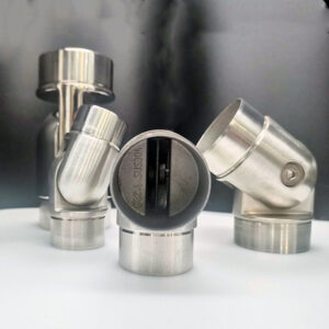
Corner Post Engineering
At an outside corner, cables from two perpendicular runs converge on a single post. This necessitates precise 90-degree alignment of cable holes and may require specialized pass-through fittings to manage the cable paths cleanly. The corner post becomes a critical load concentration point, often requiring more robust mounting.
The Need for Advanced Support
These scenarios are where traditional text-only instructions fail at a high rate. We compared project success rates and found that installers using integrated video libraries for complex applications like stairs completed projects 40% faster with fewer errors. This makes searchable, scenario-specific technical support a direct driver of reduced warranty claims and a competitive advantage for suppliers of complete cable railing systems and components.
Selecting the Right Fittings: Swage vs. Swageless
Permanent vs. Adjustable Connections
The choice between swage and swageless fittings is a fundamental project decision. Swage fittings create a permanent, professional-grade connection but require a significant investment in a specialized crimping tool. Swageless fittings offer field-adjustability and re-tensioning capability using standard tools, simplifying both installation and future maintenance.
Tooling and User Segmentation
This distinction effectively segments the market. Swage systems are the domain of high-volume professionals for whom tool cost is amortized. Swageless systems cater to the “professionalization” of the skilled homeowner and contractors who value adaptability. Manufacturers are responding with hybrid “Pro-Am” product tiers that offer advanced features without full contractor-grade complexity.
The decision matrix can be clarified with a direct comparison:
Swage vs. Swageless Fitting Comparison
| Feature | Swage Fittings | Swageless Fittings |
|---|---|---|
| Connection Type | Permanent crimp | Mechanically locked |
| Primary Tool | Specialized crimper | Standard Allen wrench |
| Adjustability | None | Field-adjustable |
| Ideal User | Professional contractor | DIY & contractor |
Source: Technical documentation and industry specifications.
Long-Term Maintenance and Inspection Guidelines
Proactive Inspection Protocol
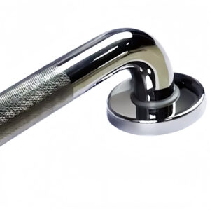
Stainless steel systems are low-maintenance but not no-maintenance. A bi-annual inspection is recommended. Check all hardware for tightness, ensure cables cannot be deflected to create a 4-inch gap, and verify overall structural rigidity. Annually, inspect for signs of corrosion, particularly in coastal environments, and apply appropriate protective treatments if needed.
The Reality of Cable Relaxation
Cables will naturally relax over time and require re-tensioning. This process must follow the same middle-out, alternating sequence used during initial installation. This predictable need creates a post-installation service opportunity. Forward-thinking contractors bundle first-year maintenance checks or offer service contracts, building recurring revenue and enabling early detection of potential issues.
Scheduled Maintenance Tasks
A clear schedule prevents neglect and ensures system longevity.
Recommended Maintenance Schedule
| Task | Frequency | Key Action |
|---|---|---|
| Full System Inspection | Bi-annually | Check hardware tightness |
| Cable Cleaning | As needed | Mild soap solution |
| Re-tensioning Check | Annually | Follow middle-out sequence |
| Corrosion Check | Annually (coastal) | Apply protective treatments |
Source: Technical documentation and industry specifications.
Final System Check and Common Installation Pitfalls
Comprehensive Pre-Completion Audit
Before deeming a project complete, conduct a methodical final inspection. Verify every fitting is secure and that the middle-out tensioning sequence was followed, checking for any post distortion. Inspect all cable holes for sharp edges; any abrasion point must be sleeved. Ensure the entire run is plumb, level, and rigid with no excessive sway when force is applied.
Cataloging Frequent Failures
Common installation failures are predictable and often interconnected. Inadequate post spacing remains the top cause of excessive deflection. Improper mounting to insufficient framing—such as deck boards without blocking—leads to gradual pull-out. Misaligned cable holes create friction and wear, compromising cable integrity. These are not minor cosmetic issues; they are systemic safety compromises.
The Evolving Market Landscape
This depth of technical complexity favors integrated solutions. The market is consolidating around platform providers who offer complete systems—posts, cables, fittings, and comprehensive support—ensuring compatibility and performance. This trend pressures pure-play cable manufacturers to either niche specialize or expand their offerings to remain competitive. For the installer, partnering with a technical resource that understands the full structural picture, from wood post design to cable dynamics, is no longer a luxury but a necessity for efficiency and liability management.
The core decision points are clear: prioritize structural spacing over material economy, select a termination system that matches your tooling and future needs, and adhere to a disciplined tensioning sequence. Compliance is not a final step but a design prerequisite that must be verified against local codes. For stairs and complex layouts, leverage advanced planning and visual guides.
Need professional-grade components and technical support for your next railing project? Explore engineered solutions and detailed specifications at Esang. For direct consultation on your specific application requirements, you can also Contact Us.
Frequently Asked Questions
Q: What is the maximum recommended spacing for cable railing posts to ensure structural stability?
A: Post spacing is the primary factor controlling cable deflection and handrail strength. For cable support, intermediate posts should be placed at least every 4 to 4.5 feet to limit lateral bowing. Handrail support to prevent sag typically requires a maximum span of 8 feet. For projects where minimizing material cost is a priority, you must still respect these spacing limits to avoid system failure and costly callbacks.
Q: How do building codes impact the design of cable railing infill spacing?
A: Codes universally enforce the 4-Inch Sphere Rule, prohibiting a 4-inch sphere from passing through any opening. This has established a de facto industry standard of 3 to 3 ⅛ inches for maximum vertical cable spacing. Compliance with guardrail height requirements, typically 36 to 42 inches for residential decks, is also mandatory. This means contractors must master local code amendments and permitting processes to avoid failed inspections, adding a critical consulting layer to their service. The ICC A117.1 standard provides detailed specifications for these safety parameters.
Q: What is the correct sequence for tensioning cables to prevent post warping?
A: The tensioning sequence is as vital as the final tension value for even load distribution. Always begin with the middle cable and work outward towards the top and bottom, alternating sides. This prescribed method prevents posts from twisting or pulling out of alignment. For installations where long-term system rigidity is critical, following this middle-out alternating sequence is a non-negotiable quality control step.
Q: When should I choose swageless fittings over traditional swage fittings for a cable system?
A: Choose swageless fittings for projects requiring field adjustability, re-tensioning capability, or tool minimization, as they install with standard Allen wrenches. Swage fittings create a permanent, professional-grade crimp but require a specialized tool. This means DIY installers and contractors prioritizing future maintenance should select swageless systems, while high-volume professional shops may prefer the efficiency of bulk swage components.
Q: How do you properly mount wood posts for a cable railing to meet structural load requirements?
A: Mounting must transfer tension and live loads to solid structural framing, such as reinforced deck blocking or concrete. Every post must be plumbed and leveled before final fastening to ensure proper alignment. For wood construction, the structural design of posts and connections must comply with engineering standards like the NDS for Wood Construction to withstand required guardrail forces.
Q: What are the key maintenance tasks for a stainless steel cable railing system?
A: Proactive care includes bi-annual inspections for hardware tightness and cable deflection, annual checks for corrosion, and periodic cleaning with a mild soap solution. Cables will naturally relax and require re-tensioning using the proper middle-out sequence. This creates a post-installation service opportunity; contractors can bundle first-year maintenance kits to build recurring customer relationships and enable early problem detection.
Q: What are common installation pitfalls that lead to cable railing system failure?
A: Frequent failures include inadequate post spacing causing excessive deflection, improper mounting to insufficient framing, and misaligned cable holes creating abrasion. Over-tensioning stresses the entire structure, while neglecting the prescribed tensioning sequence can warp posts. This complexity underscores why successful installers rely on comprehensive technical resources and often favor integrated system providers over sourcing individual components.