A retrofit surface mount handrail survey succeeds or fails on one question: what is actually under the base plate, and how much of it is structural. Before any fabrication dimension leaves the office, the survey needs to separate the structural substrate from tile, screed, caps and coatings; record edges, thicknesses, slopes, landings and terminations from a consistent datum; mark concealed reinforcement, services and uncertain construction for verification before drilling; and label every figure as measured, assumed or still open. Surface mounting means the post base sits on the finished surface and transfers guard loads through anchors into whatever lies beneath, so a survey that reports one combined thickness gives the designer nothing usable.
Identify the Structural Substrate Beneath Existing Finish Layers
| Survey classification | Record separately | Límite de decisión |
|---|---|---|
| Structural substrate | Identified substrate, available thickness information, and edge condition | Use the recorded condition for project verification before drilling; do not infer it from the finish build-up. |
| Finish build-up | Tile, screed, caps, coatings, and any other layer above or around the substrate | Keep finish thickness and likely repair scope separate from the structural-substrate record. |
The first job on site is to decide which layer is structural and which layers are simply sitting on top of it, then record them separately. A 40 mm build-up of tile and bedding over a slab is not 40 mm of anchorage; it is a non-load-bearing layer that the anchor must pass through before it reaches material that can resist tension and shear. Combining them into one measurement is how a base plate ends up anchored in screed.
Henkel’s Ceresit CF850 and CF920 chemical anchoring handbook makes this distinction explicitly in its base-material discussion: supporting masonry is treated separately from plaster or insulation, and embedment is counted in the actual substrate, with non-load-bearing layers counted separately from the supporting base. The same handbook relates drilling depth to member thickness under the anchor approvals, and notes that proximity to an edge affects anchorage behavior. For a survey record, that means three distinct entries at each proposed base: what the substrate is, what thickness information is available for it, and what the edge condition is nearby.
Finish build-up still belongs in the record, but for a different reason. It governs how deep the hole has to run before useful embedment begins, whether the base plate sits on a compressible or brittle layer, and how much tile, coating or topping will be disturbed around each post. Keeping that figure in its own column keeps it available for the repair-scope discussion without letting it inflate the structural picture.
Where the substrate cannot be identified with confidence — a concrete topping over hollow units, an unknown timber deck structure, a rendered masonry upstand — say so plainly in the record and mark it for project verification before drilling. The substrate identification is not a judgment the surveyor can close out from the surface alone, and the anchor selection depends on it.
Measure Edges, Thicknesses, Slopes, Landings, and Terminations From Fixed Datums
| Geometry to survey | Record from the fixed datum | Decision supported |
|---|---|---|
| Edges and available thicknesses | Edge locations, available thickness information, and edge condition | Check proposed post positions against the recorded edge geometry and available thickness. |
| Nosings and landings | Dimensions and locations from the same datum | Establish the landing and nosing geometry used for the post layout. |
| Slopes and changes in direction | Dimensions and locations of each slope or directional change | Keep changes in geometry visible when fabrication dimensions are prepared. |
| Termination points | Exact location of each termination | Define where the surveyed handrail run ends. |
| Obstructions | Location and relevant dimensions relative to the proposed layout | Flag layout constraints before fabrication data is released. |
Every dimension in a retrofit survey should trace back to the same physical datum, because the fabricator will set out the handrail from a single origin and any dimension measured from a moveable feature will not reconcile. Pick something permanent — a structural column face, a finished floor level at a defined location, a building grid line that is visibly set out on site — and run the whole survey from it. Measuring one flight from the bottom nosing and the next from a landing edge produces two internally consistent sets of numbers that will not join up in the shop.
The geometry that matters for a surface-mount layout is the geometry that constrains where a base plate can physically sit. Edge distance comes first: the horizontal distance from the proposed anchor to the nearest free edge of the structural substrate, not to the edge of the tile. Available substrate thickness comes next, because it limits embedment. Then the features that fix the post positions themselves — nosings, landing extents, slope changes, and the points where the handrail turns, steps or terminates.
Changes in direction deserve their own dimensions rather than being inferred from a general angle. A stair that appears to run straight may carry a small plan skew, and a ramp that reads as a constant slope may include a transition. Both show up as fabrication errors in a welded or preassembled run, because the top rail is cut to length before anyone is standing on the stair again.
Obstructions belong in the same register as the geometry they interfere with. A downpipe, a door swing, a floor box or a projecting plinth can rule out an otherwise sensible post position, and the useful record is the obstruction’s location and the dimensions that matter relative to the proposed layout, not a note that something is in the way. Survey the termination points with equal care: where a run ends against a wall, a column, a newel or nothing at all determines the end detail and often the end-post loading.
Map Reinforcement, Services, Joints, Damage, and Unknowns Before Drilling
| Condition group | Map and cross-reference | Decision boundary before drilling |
|---|---|---|
| Concealed reinforcement and services | Available location information, drawing position, and any location uncertainty | Mark uncertain locations for project verification before drilling. |
| Joints and edge conditions | Observed location relative to the proposed post layout | Check the proposed layout against the recorded interface or edge condition. |
| Cracks and patches | Exact drawing location and linked photograph | Carry the observed condition into the base-location and likely repair-scope review. |
| Uncertain construction | Affected area, the assumption being made, and the open investigation | Keep the uncertainty explicit until project verification is recorded. |
Mapping concealed conditions is a separate exercise from measuring geometry, and it decides whether a proposed anchor position is drillable at all. Reinforcement, post-tensioning, conduit, live wiring, timber substructure and buried pipework all sit under surfaces that look identical from above, and the surface finish tells you nothing about which of them is present.
Scanning is the practical way to plan this investigation rather than guessing. Hilti describes its PS 85 wall scanner as a tool for locating embedded objects before drilling or cutting — reinforcement, live wiring, timber substructures and metal or plastic pipes — and states that it scans through concrete, brick, drywall and tiles, with usable detection depth depending on the material. That material dependency is the point for a surveyor: the same instrument gives different reach through a tiled screed than through plain concrete, and detection is an aid to planning the investigation, not a clearance to drill. Where a scan result is uncertain, the honest entry is the location, the uncertainty, and the verification that remains open.
Joints and interfaces need mapping because they change what the substrate can do locally. A movement joint, a construction joint, a slab edge, a nosing return or a junction between two different constructions all affect how close an anchor can sit and how the base behaves under load, and the record should show where each one falls relative to the proposed post layout rather than simply noting that joints exist.
Cracks, patches, spalling and previous repairs are condition information, and FHWA’s guidance on detecting and treating materials-related distress in concrete pavements makes a distinction worth carrying over: recording visible distress is not the same as establishing its cause, which can require further investigation. Record the exact drawing location of each observed crack or patch, link it to a photograph, and carry it into the base-location review — but leave the diagnosis and the decision about whether that location is acceptable to the project’s design and approval process. Where an area of construction simply cannot be characterized from the surface, write down the affected extent, the assumption being made, and the investigation that is still open, and keep it visible until project verification is recorded.
Record Installation Access and the Likely Repair Scope Around Each Base
Access determines whether a surveyed post position can actually be installed, and it is cheaper to discover that on the survey than on the day. At each proposed base, note what the installer needs to get into the space: drill length and the clearance above the anchor point, room to swing a torque wrench or a socket, the working position on a stair where the operator cannot stand square to the hole, and whether a platform, trestle or scaffold is required to reach a landing nosing or an elevated edge.
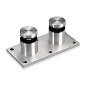
Several access constraints only appear when the mounting method is considered alongside the geometry. Surface-mount bases need clear floor area for the plate footprint plus cover-plate removal; anchors near a wall or a riser face may not accept a straight drill. Where the handrail is wall-mounted instead, the load path changes entirely — the wall must take the fixing loads rather than the floor — so the access question becomes whether the bracket positions fall on structural wall material and whether the drilling angle is achievable between the rail and the wall surface. Recording the constraint at the specific base, rather than as a general site note, is what makes it actionable.
Repair scope follows directly from the finish build-up already recorded. Drilling through tile, stone, resin coating, deck boards or waterproofing creates a disturbed zone around each anchor, and someone has to make good, reseal or reinstate it. Note the finish type at each base, the approximate area that will be disturbed by the plate footprint and drilling, and whether a waterproof membrane, a tanking layer or a trafficked coating is involved — those carry consequences beyond cosmetics, because a penetration through a membrane is a detail that has to be designed, not simply filled.
Existing fixings and voids left by a removed balustrade belong in the same record. Old core holes, grouted sockets, sheared studs and previous patches may sit exactly where a new base plate wants to go, and whether an existing hole is reused, filled or avoided is a design and approval decision, not a site improvisation. Record the position and condition of each one and let the project’s approved procedure and its designated approver decide how it is treated.
Pair Photographs With Drawing Locations and Proposed Post Positions
| Photograph subject | Cross-reference to add | Layout relationship to show |
|---|---|---|
| Crack | Photograph identifier and exact drawing location | Position relative to the proposed base or post |
| Patch | Photograph identifier and exact drawing location | Position relative to the proposed base or post |
| Joint | Photograph identifier and exact drawing location | Position relative to the proposed base or post |
| Access constraint | Photograph identifier and exact drawing location | Constraint at the affected proposed base or post position |
A photograph is only useful if someone reading it months later can say exactly where it was taken and what it shows relative to the proposed layout. The method is simple and should be applied without exception: give each photograph an identifier, mark that identifier at its exact location on the survey drawing, and note the relationship between what is photographed and the nearest proposed base or post position.
FHWA’s condition-survey guidance for concrete pavements uses the same combination — construction information, photographs, a sketch map, alignment and defect records — and the principle transfers directly to a handrail survey. The sketch map is what turns a folder of images into evidence, because it fixes the location; without it, a photograph of a crack is a photograph of a crack somewhere.
Three subjects are worth photographing at every run: observed damage such as cracks, spalls and patches; interfaces such as joints, substrate changes and nosing details; and access constraints that affect drilling or lifting. Shoot each with a scale reference and at least one frame wide enough to show the surrounding context, so the reviewer can place it against the drawing without relying on memory.
The post layout is the organizing frame for all of it. When a photographed crack falls within the footprint of a proposed base plate, or an access constraint sits at a specific post position, that relationship is the finding — not the photograph itself. Noting it at the time keeps the layout review quick and keeps the fabricator from setting out posts into conditions the survey already captured.
Release Fabrication Data Only After Assumptions and Open Investigations Are Flagged
| Survey status | How to identify it | Treatment in fabrication data |
|---|---|---|
| Measured condition | Record the measured value or condition with its fixed datum and drawing location | Present it as measured only when the survey record is complete. |
| Assumption | State the assumed value or condition and distinguish it from measured information | Flag it explicitly; do not present it as a field measurement. |
| Open investigation | State the affected location and the verification that remains open | Keep it visible as an unresolved project-verification item before release. |
Fabrication dimensions should leave the survey only when every figure in the package carries its status: measured, assumed, or subject to an open investigation. Once a number enters a shop drawing it is treated as fact, and an assumed substrate thickness or an estimated landing dimension that was never labeled will be cut to length in steel.
A measured condition is one taken on site, referenced to the fixed datum, and located on the drawing. An assumption is a value adopted because the condition could not be observed — a substrate type inferred from the building’s age, a thickness taken from an archive drawing, a reinforcement position read from a record rather than a scan. Both can appear in the same package, but they must not look the same. An open investigation is narrower still: a named location with a named verification that has not yet been done, which stays visible until it is closed out by project verification.
The practical discipline is to write the assumption down with its reason at the moment it is made, not to reconstruct it later. The surveyor who assumes a concrete slab under a tiled landing knows exactly why in that moment; two weeks on, the assumption reads as a measurement. The same applies to the shop-drawing review, where post spacing, base plate sizes and anchor positions are checked against the recorded conditions — the review only works if it can tell which recorded conditions were actually seen.
Whether a given assumption is acceptable to carry into fabrication is not a survey decision. Guard loading, anchorage capacity, post spacing and the acceptability of a crack or an edge distance at a particular base all sit with the project’s design and its designated approver, and the survey’s job is to put the facts and the gaps in front of them in a form they can act on. For a productive conversation with a railing supplier about a retrofit, have ready the marked-up survey drawing with proposed post positions, the substrate and finish records at each base, the photograph cross-reference, the dimensioned geometry from the fixed datum, the specified stainless grade and finish for the exposure, and an explicit list of what is still assumed or under investigation.
Preguntas frecuentes
P: What information should be ready before the retrofit handrail site survey begins?
A: Bring the proposed post layout, available construction information, and known access or finish-repair constraints. Use the survey to distinguish verified field conditions from drawing information and assumptions, and identify the exact locations that still need investigation.
P: Can the same survey record be used to compare alternative post layouts?
A: Yes, if geometry is measured from a consistent datum and site conditions are mapped independently of one proposed layout. Each alternative post position still needs to be checked against edges, available thickness, joints, damage, obstructions, and known or uncertain concealed items.
P: When should an uncertain site condition remain open before drilling?
A: Keep it open when the missing fact could affect the substrate, edge condition, available thickness, concealed reinforcement or services, access, or repair scope at a proposed base. Record the affected location and the specific verification required rather than treating the assumption as a measured condition.
P: How should the likely repair scope be prepared for pricing and coordination?
A: Define it by proposed base location, separating work to tile, screed, caps, coatings, and other finishes from the structural-substrate record. Cross-reference nearby cracks, patches, joints, and access constraints so the project team can review what may need removal, protection, or reinstatement at each location.
P: Does completing this survey checklist confirm that the retrofit handrail meets every applicable requirement?
A: No. The checklist organizes field conditions for layout, drilling, repair, and fabrication decisions; it does not establish universal code or specification compliance. Confirm the project-specific design criteria, applicable requirements, and any unresolved field conditions before treating the fabrication data as ready for use.