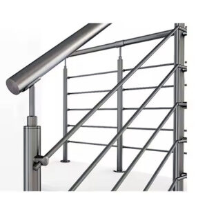
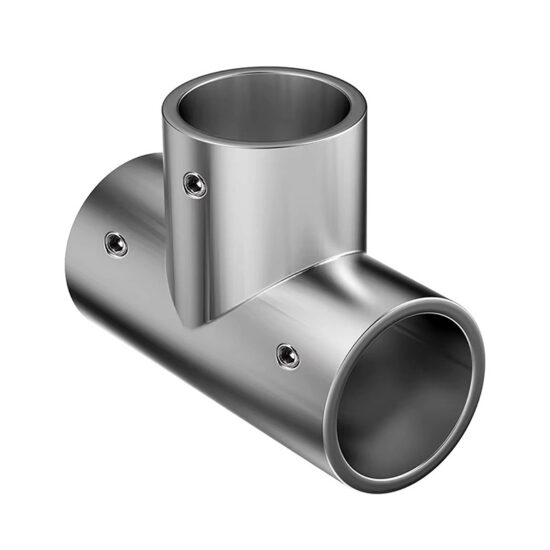
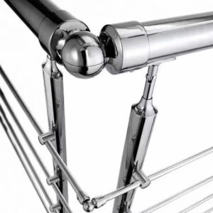
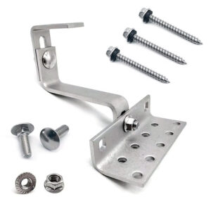
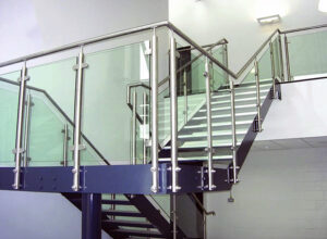
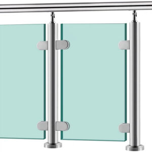
A stair run, a landing, and the transition between them can all use mesh infill, but they do not take the same panel geometry. Assigning “level” panels to a sloped opening, or a raked panel to a horizontal one, produces a mismatch at the frame and fixing points before anyone reaches a finish or material discussion. The choice belongs to whoever controls the run drawings, and it needs to be made before a mesh panel is ordered rather than discovered at installation.
Name the Run Before Choosing the Panel Geometry
Every railing run has a physical condition that exists independent of any panel catalog: it is level, it is consistently sloped, or it changes from one to the other somewhere along its length. That condition is a project fact, established by the stair, ramp, or landing geometry as built or designed, not something a supplier can infer from a product name or assume from a photograph of a similar-looking installation elsewhere.
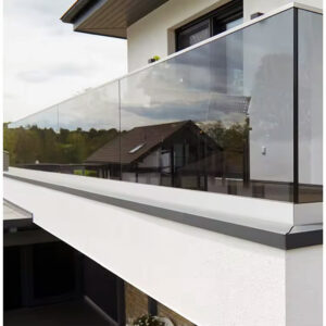
Where a run is level throughout, the opening the mesh panel fills has parallel top and bottom boundaries, and the panel geometry can follow a simple rectangular logic. Where a run is consistently raked, as on a stair flight, the opening is bounded by parallel sloped members, and the panel must accommodate that angle at every edge, not just at the ends. Where a run transitions between level and sloped segments — at a stair-to-landing junction, for example — the opening geometry itself changes shape partway through the run, and the panel or panels covering that stretch must resolve the change in slope somewhere within the frame or across an adjoining pair of panels.
This distinction matters because the same nominal panel width or height can describe entirely different fabricated shapes depending on which of these three conditions applies. A designer who specifies mesh infill by dimension alone, without stating which run condition produced that dimension, leaves the fabrication logic underspecified. The supplier reviewing the order cannot determine from a width and height alone whether the top and bottom edges are parallel, angled, or mixed.
Corner and irregular conditions add a further layer: where a run turns a corner, or where an irregular boundary interrupts an otherwise consistent slope, the relationship between adjacent panels becomes part of the geometry decision, not an installation detail resolved later. A panel schedule built without capturing these transition and corner points leaves gaps that surface only when panels arrive and do not align with their neighbors.
| Run condition | What the drawings should show |
|---|---|
| Level | Horizontal opening and bounding members |
| Raked/stair | Consistent slope and start/end geometry |
| Transition | Change between level and sloped conditions |
| Corner or irregular | Adjacent-run relationship and unique corner points |
Understand the Three Geometry Labels
Indiana Wire Products, a specialist wire-product manufacturer, offers infill panels described as level, raked, and raked-to-level, and that three-part naming gives the reader a working vocabulary for matching panel geometry to run condition. A level panel is built to serve a level opening: its bounding frame members run parallel and horizontal, and the mesh pattern sits within that rectangular boundary without needing to resolve any angle. A raked panel is built to follow a sloped opening: the frame members run parallel to each other but at the rake angle of the stair or ramp, so the entire panel — frame and mesh alike — is oriented to that slope.
Raked-to-level is the more complex condition, and it deserves caution rather than a confident restatement of exact construction. It describes a sloped frame condition in which the wire orientation is arranged relative to the frame’s vertical or horizontal members rather than simply following the rake of the frame itself. In practical terms, this is the geometry that lets a designer keep the mesh pattern visually level or vertical even while the panel as a whole sits within a raked opening. But how a given manufacturer constructs that relationship — which members the wires reference, how the frame accommodates the resulting geometry — is a supplier-specific detail. The label identifies a category of solution; it does not by itself specify the construction.
This is the distinction most directly at stake in the article’s title question, because choosing among level, raked, and raked-to-level is not simply a matter of matching a panel to a run shape. A raked run can be filled with a raked panel, whose mesh follows the slope, or with a raked-to-level panel, whose frame follows the slope while the mesh orientation references something else. Both are valid answers to “what fills this sloped opening,” and the choice between them depends on what the designer wants the mesh pattern itself to do visually, which is a separate question from the run’s physical shape. A buyer who states only “this run is sloped” has supplied the frame condition but not yet the mesh-orientation intent, and a supplier cannot resolve that gap without asking.
| Geometry label | Core concept | Confirmation needed |
|---|---|---|
| Level | Panel serves a level opening | Finished panel and fixing dimensions |
| Raked | Panel/frame follows a sloped opening | Rake geometry and mesh/frame relationship |
| Raked-to-level | Sloped panel condition with wires oriented relative to vertical or horizontal frame members | Exact frame shape, wire orientation, and supplier construction |
Decide What the Mesh Pattern Should Reference
Once the run condition and the frame geometry are settled, a separate decision remains open on sloped runs: what should the mesh pattern itself visually reference? This is not a restatement of raked versus raked-to-level: it is the underlying design intent that makes that earlier choice meaningful. A mesh pattern can follow the sloped frame directly, producing wires that rake with the stair. It can instead hold to a horizontal or vertical datum independent of the frame’s slope, producing the visual effect that raked-to-level construction is meant to achieve. Or a project may state another visual requirement entirely, tied to a design line that does not map neatly to either the frame or a simple horizontal/vertical reference.
Where a run sits in isolation, this choice mostly affects that single run’s appearance. Where a raked run sits adjacent to level panels — at the top or bottom of a stair flight, for instance — the orientation decision also determines whether the mesh pattern reads as continuous across the transition or breaks visibly at the junction. A pattern that follows the frame will change angle exactly where the frame changes angle; a pattern held to a level datum may appear to continue more smoothly into an adjoining level panel, or may instead create its own visible discontinuity depending on how the transition panel resolves the change. Neither outcome is inherently correct: it depends on whether the project wants the run boundaries or the visual mesh line to read as the dominant feature.
Project examples described by manufacturers such as Indiana Wire Products illustrate that frame slope and mesh orientation can be coordinated in more than one way; they do not establish which coordination a given project should use, and they do not confirm that every combination is available from every supplier. What they support is the general point that this is a decision to be made deliberately, not a byproduct of whichever construction a supplier defaults to. A designer who has not stated an orientation preference has left this open, and the eventual answer will affect how the panel schedule describes each panel mark.
| Orientation question | Record on the project documents |
|---|---|
| Reference | Frame edge, horizontal datum, vertical datum, or stated design line |
| الاستمرارية | Whether adjacent level and sloped runs should align visually |
| Pattern behavior | Direction expected through corners and transitions |
| Open issue | Supplier feasibility requiring confirmation |
Map Geometry to Posts, Rails, and Panel Edges
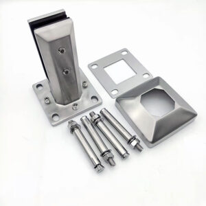
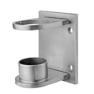
A mesh panel does not exist independent of the assembly that holds it. Once the run condition and the geometry label are chosen, the panel’s edges, fixing points, and corners must be coordinated with the posts and rails that bound it, because the panel geometry and the surrounding hardware geometry are two descriptions of the same physical interface.
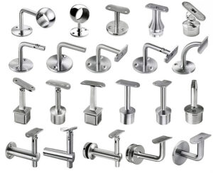
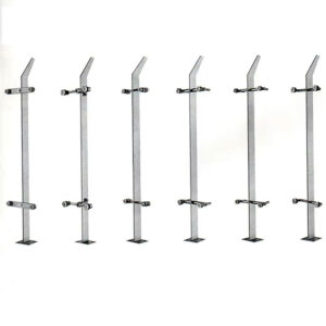
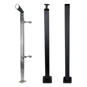
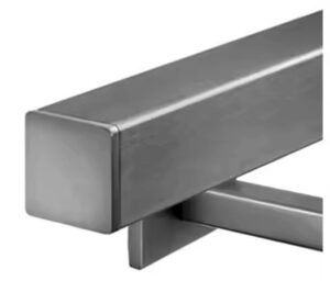
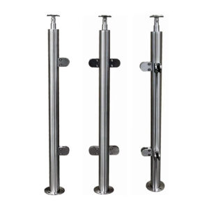
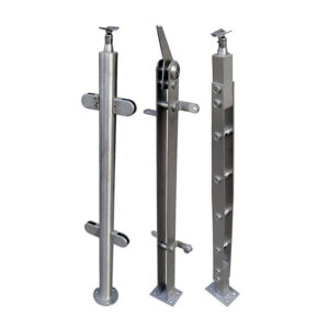
Post positions and shapes determine where the panel’s vertical edges terminate and how those edges connect. On a raked run, the angle between post and rail is not the same as on a level run, and a panel edge or fixing built for one relationship will not necessarily suit the other without adjustment. Top and bottom rail profiles carry a related consequence: where the rail itself is a continuous sloped member, the panel’s top and bottom edges must be built to meet that member’s angle and profile consistently along its length, and where the rail changes profile or terminates at a landing, the panel edge nearest that point carries the transition.
Frame and edge treatment decisions affect not just structural fit but visible intent: an edge condition that looks acceptable on a level panel may expose a mismatched angle if applied without adjustment to a raked one. Fixing locations follow a similar logic — where fixings are positioned relative to a level baseline on a level panel, the equivalent fixing on a raked panel must be positioned relative to the slope, and that relationship needs to be stated rather than assumed to translate directly.
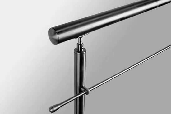
Adjacent-panel relationships close the loop: a raked panel meeting a level panel at a transition point has a handed condition — left or right, ascending or descending — that determines which panel’s edge treatment governs the joint. This is where reviewing available options for wire mesh infill panels alongside the top rails and bottom rails they attach to becomes useful, since the geometry decision cannot be finalized by evaluating the panel or the rail in isolation from the other.
| Interface | Geometry information required |
|---|---|
| المنشورات | Positions, shape, and connection locations |
| Top/bottom rails | Profiles and start/end relationships |
| Frame/edge | Corner points and visible edge intent |
| Fixing | Locations and relationship to the slope |
| Adjacent panel | Level/raked transition and handed condition |
Freeze the Geometry Through Drawings and a Panel Schedule
None of the geometry decisions above are complete until they exist as coordinated project documents rather than verbal descriptions. UFGS 05 52 00, the government guide specification for metal railings, supports the general principle that plans, elevations, detailed sections and connections, member dimensions, accurate angles, and coordinated fabrication drawings are what document run geometry in a form a fabricator can act on — it is project-editable guidance rather than a drawing already prepared for this project, but the underlying requirement holds regardless of project: geometry stated only in narrative form is not yet geometry a supplier can fabricate against.
A panel schedule turns the run-by-run decisions into an ordering instrument. Each panel needs a unique mark tied to its location on the plan or elevation, the dimensions or corner coordinates the project has established for that opening, the mesh orientation decided for that panel, and the quantity required. Where a run includes a transition or a handed condition, the schedule is where that distinction is recorded so it is not left to be resolved again at delivery. Where feasibility questions remain — whether a particular raked-to-level construction is achievable at a given angle, for instance, or whether a transition panel can be built as a single piece rather than two — the schedule should carry those as open items requiring supplier confirmation, rather than silently resolving them by omission.
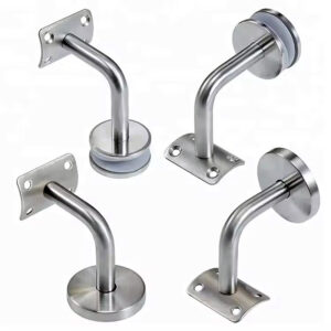
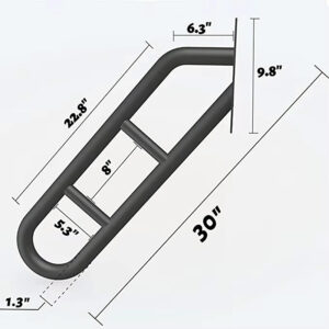
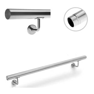
This is the stage at which project information supplied by the customer enters ESANG’s configuration or quotation review: dimensions, corner coordinates, orientation decisions, and panel marks recorded on drawings and in a schedule give a supplier something concrete to check against fabrication capability, rather than a description that still requires interpretation. What a frozen geometry set does not do is substitute for engineering review, code compliance, or installed-system approval. Those remain separate steps, assessed against the specific installation once the geometry itself is no longer in question. A related sloped-run hardware condition — adjustable handrail brackets for stairs, ramps, and uneven site conditions — illustrates that sloped runs raise coordination questions across more than one hardware category, not only at the mesh panel.
الأسئلة الشائعة
س: Is specifying a raked panel enough to tell the supplier how the wires should run?
A: No, frame slope and mesh orientation are separate design inputs. A raked frame follows a sloped opening, while the wires may reference the frame or a stated vertical or horizontal datum. Indiana Wire Products uses the raked-to-level label for a sloped condition with wires oriented relative to frame members; specify the intended shape and orientation and confirm the supplier’s exact construction.
س: Can stair panels preserve the visual alignment of mesh on an adjoining landing?
A: That can be a project design objective, but it must be stated and reviewed for feasibility. Record the desired pattern reference and continuity across the level and sloped runs, including corners and transitions. The geometry label alone does not establish the visual result or a feasible panel construction.
س: What information should accompany a mixed level-and-stair panel inquiry?
A: Identify each run condition and panel mark, with project-issued dimensions or corner points, mesh orientation, and quantity tied to plans and elevations. Include post positions, rail profiles, edge or frame details, fixing locations, and handed relationships between adjacent panels. Keep any unresolved transition or construction question explicit for supplier review before geometry is frozen.