Every corner, return, and slope transition in a post-mounted handrail run carries its own geometry logic, and treating two different transitions as interchangeable is how fabrication drawings end up with the wrong extension or a return that misses the wall by a few degrees. The question facing the buyer is not whether a corner or a termination is needed, but which specific geometry each direction or elevation change requires, and what information must be locked before connectors and posts are selected.
Geometry Inputs That Define Each Direction Change
| Layout input | What to show | Decision supported |
|---|---|---|
| Rail centerline | Centerline through each direction and elevation change | Establishes the reference for laying out the transition |
| Direction and elevation changes | Each change located on the rail centerline | Defines the required transition geometry before brackets and connectors are released |
| Posts and supports | Locations coordinated around the required transition geometry | Confirms that support placement follows the planned transition |
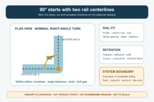
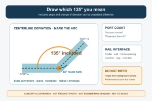
Every transition in a handrail run starts from the same reference: the rail centerline. Laying out a corner, a slope change, or a termination without first establishing that centerline invites mismatched post spacing and connector angles that only surface during fabrication or field fit-up. The centerline is not a drafting convenience; it is the line against which every direction change, elevation change, and support location gets measured and checked for consistency.
A plan-view angle shows where a rail turns in one axis, but a run that changes slope — a stair flight meeting a landing, or a ramp run meeting a level walk — changes in a second axis that a plan view alone cannot capture. Reading plan and elevation together is what separates a true transition requirement from an assumption based on partial information. Where a design shows only a plan-view bend, the buyer should ask whether an elevation change accompanies it, because the fitting and bracket geometry for a level corner differs from what a sloped-to-level transition demands.
Posts and supports are placed in relation to the transition geometry, not independently of it. Once the centerline and the location of each direction or elevation change are fixed, post and support positions follow from where the geometry forces a structural pickup near the turn or slope break. If supports are located first and the transition geometry is adjusted afterward, the result is often a bracket or connector that no longer lines up cleanly with the post it was meant to anchor against.
The practical consequence for a buyer evaluating a shop drawing or a layout proposal is that the drawing should show the centerline, the direction and elevation changes located on it, and the posts and supports positioned in response to those changes — in that order of derivation. If a drawing shows posts first with transitions implied afterward, that sequence should prompt a question rather than an assumption, because it reverses the logic that keeps a transition buildable. Where a project includes several direction changes in close sequence, each one still needs its own centerline-based definition; treating a cluster of changes as one generic “corner condition” risks collapsing distinct geometries into a single assumed detail.
Corner Details for Level, Stair, and Ramp Runs
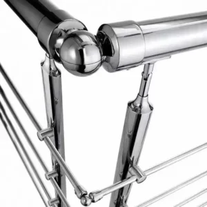
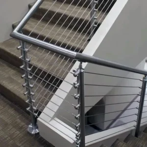
A corner on a level run, a corner within a stair flight, and a corner or slope break on a ramp are not the same condition, even where they look similar in a plan sketch. A level corner changes only direction; the rail stays at a constant height relative to the walking surface on both sides of the turn, so the connecting fitting only needs to resolve an angle in one plane. A stair corner — an inside switchback or dogleg turn within a flight — changes direction while the rail continues to follow a sloped relationship to the nosings on both sides, so the fitting at that turn has to resolve an angle while preserving the slope relationship on each leg.
A ramp corner or transition point introduces a further distinction: where a ramp run meets a landing or a level walk, the rail may change from a sloped condition to a level one at the same point where it also changes direction, or those two changes may occur at separate points along the run. Confirming which condition applies changes which fitting geometry is appropriate, because a connector built to resolve a direction change alone will not correctly carry a simultaneous slope change.
This distinction matters directly for continuity. On a covered stairway, the usual handrail condition is continuous along each flight and around inside switchback or dogleg turns, following the Access Board’s Chapter 5 guidance for stairways within its scope. That continuity requirement means an inside stair turn is typically a through-connection rather than a termination, which changes the component selected at that point from a terminal fitting to a continuous-run connector. A ramp corner does not automatically carry the same continuity expectation; whether a given ramp turn is a continuous pass-through or a point where the rail terminates and a new extension begins depends on the project’s layout and where the extensions are required, following the Access Board’s Chapter 4 guidance on ramps within its covered scope.
The buyer’s task at each corner is therefore to identify, before specifying a fitting, whether the condition is level, stair, or ramp; whether the direction change and any elevation change occur together or separately; and whether continuity or termination applies at that specific point. None of these can be read reliably from an isolated plan-view angle.
Terminal Returns and Handrail Continuity
A terminal return and a required extension solve different problems, and confusing them produces a rail end that looks finished but fails the geometry a covered project needs. An extension is the length of rail that continues past the point where support or guarding is structurally required, positioned to give a hand a lead-in or run-out before or after the functional part of the rail. A return is the detail that brings the end of that extension back to a wall, guard, or floor, closing off the open end so it does not project as a hazard.
Where a stairway is covered by accessibility requirements, the Access Board’s Chapter 5 guidance describes the usual terminal condition as asymmetric: the top extension is horizontal for a stated minimum distance, while the bottom extension follows the slope of the stair for a stated minimum distance beyond the last riser nosing. These are different shapes serving different functions — the top extension signals the start of the descent before the hand reaches it, and the bottom extension continues the sloped gripping surface past the last step. A detail that copies one end’s geometry onto the other end misreads the requirement, even though both ends terminate in a similar-looking return.
Ramp terminal conditions, per the Access Board’s Chapter 4 guidance, are more symmetric where covered: both the top and bottom extensions are horizontal, with an exception where the rail is part of a continuous inside switchback condition rather than a true termination. Applying a stair bottom’s sloped extension logic to a ramp end would therefore produce the wrong geometry at that location.
In every case, the return itself does not substitute for the extension; the extension length is measured to the point where the return radius begins, not to the outer edge of the return. A return that starts too early effectively shortens the extension below what the condition requires, even if the overall rail assembly appears to reach the wall or guard. Coordinating the return with the surrounding supports also means confirming that the gripping path along the top and sides of the rail remains unobstructed through the extension and into the return, since a bracket or support placed too close to the return can interrupt the continuous surface a hand would otherwise follow. Before applying any of these terminal patterns, the project team needs to confirm that the specific stairway or ramp falls within the accessibility scope assumed, since coverage and applicable exceptions determine whether these terminal geometries apply at all.
Connector, Post, and Rail Profile Compatibility
Selecting a terminal fitting or an intermediate connector before the surrounding profile decisions are finalized is a common way to end up with a component that fits the drawing but not the hardware around it. Four inputs need to be settled first: the rail profile, the post profile, the connection method, and the visible finish direction. Each of these constrains what a terminal or intermediate component can physically and visually resolve at a joint.
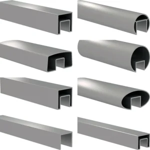
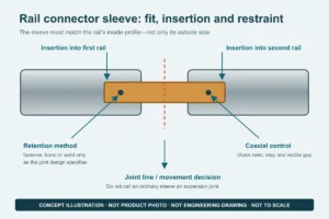
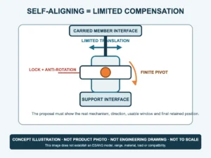
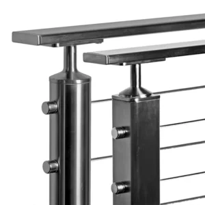
The rail profile determines the cross-section a terminal or connector fitting must accept or wrap; a change in profile — round versus a different shape, a different wall thickness or diameter — changes which fitting geometries can seat correctly. The post profile does the same on the support side: a fitting that interfaces with one post profile does not necessarily interface with another, even where both posts serve the same structural role in the run. The connection method — whether a joint is welded, mechanically fastened, or set with a specific fitting designed for a demountable or adjustable connection — determines whether the component at that joint needs to accommodate field adjustment or is fixed once installed. Where a project anticipates alignment correction after installation, a component built for a fixed connection forecloses that option; an adjustable connection method keeps it open.
Visible finish direction matters because a terminal or connector component sits at a point where the surrounding surfaces meet, and a mismatch in finish orientation at that joint is visible in a way that a mismatch mid-run often is not. Confirming finish direction before selecting the component avoids ordering a part whose finish reads correctly in isolation but conflicts with the adjoining rail or post once assembled.
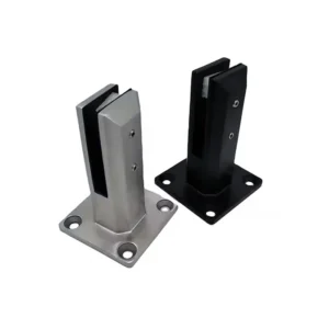
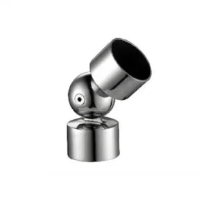
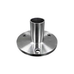
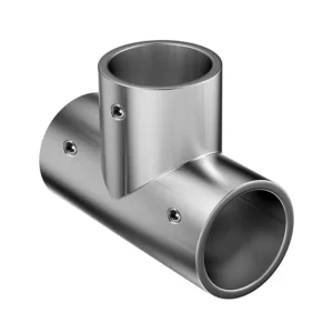
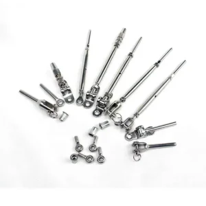
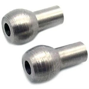
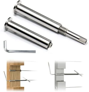
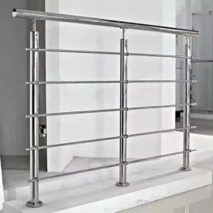
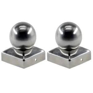
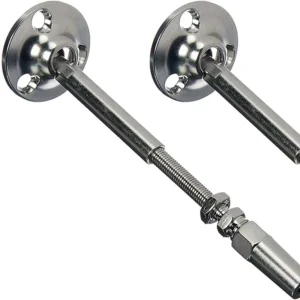
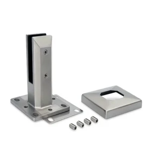
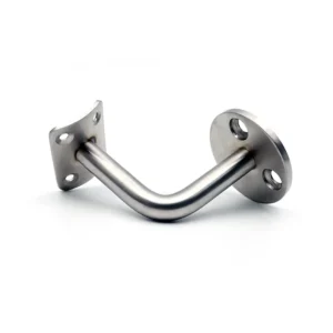
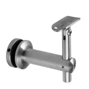
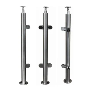
Among post-mount hardware, terminal post handrail components resolve the end conditions this section addresses, intermediate post handrail connectors resolve the through-run and corner conditions, and adjustable post handrails address projects where the connection method itself needs to accommodate variation rather than being fixed at fabrication. Choosing among these categories follows from the four inputs above, not from visual similarity between fittings; a fitting that looks suited to a turn based on its photograph may not match the specific rail profile, post profile, connection method, or finish direction the project has already committed to elsewhere in the run.
Drawing Checks Before Fabrication Release
| Release check | Evidence to verify | Release boundary |
|---|---|---|
| Component and connector selection | Rail profile, post profile, connection method, and visible finish direction are defined | Select terminal components and intermediate connectors only after all four inputs are defined |
| Corners and terminal returns | The drawing shows the project-specified handrail continuity and clearance at each condition | Do not assume one fitting suits every turn |
| Interfaces and joint locations | Interfaces and joint locations are dimensioned on the shop drawing | Fabrication and site teams can distinguish designed transitions from field adjustments |
| Project requirements | Applicable project specifications, submittals, drawings, and construction scope are identified | A guide specification provides project structure; it is not a universal code or an ESANG product requirement |
| Accessibility applicability | Project coverage and the current adopted code are verified before applying ADA stairway provisions | Access Board guidance is limited to U.S. accessibility scope and covered-facility context |
A shop drawing can show the correct fittings and still release incorrectly if the project-specific evidence behind those fitting choices is not documented alongside them. Component and connector selection should be traceable to the four profile and finish inputs already defined, and the drawing should show that each corner and terminal return reflects the specific continuity or clearance condition it belongs to, rather than a repeated generic detail applied at every turn. Where a drawing shows the same fitting at a level corner, a stair switchback, and a ramp termination without distinguishing which condition applies, that repetition is itself a signal to check rather than accept.
Interfaces and joint locations need to be dimensioned directly on the drawing, not left to be resolved in the field. The distinction between a designed transition and a field adjustment only holds if the drawing records where each joint was intended to land; without that dimension, a site team has no way to tell whether a discrepancy at installation reflects a drawing error or an intentional field condition. UFGS 05 52 00, the federal guide specification for metal railings, calls for fabrication drawings that show member dimensions and connection details with any deviations identified and explained, and calls separately for plans, elevations, sections, and connection details that support this kind of coordinated geometry — a structure a project team can reference even outside a federal contracting context, understanding that a guide specification provides drawing-coordination structure rather than a universal requirement.
Where a stairway or ramp on the project is covered by accessibility requirements, the drawing review should confirm the applicable code adoption and project scope before the Access Board’s stairway and ramp geometries are applied as the governing detail, since coverage exceptions and alterations conditions change what is required at a given location. This verification belongs in the same drawing-check pass as the geometry and interface confirmations, because a correctly dimensioned transition built to the wrong scope assumption still fails the project’s actual requirement. Information the customer provides about the specific run geometry, profile selections, and applicable project scope is what allows a fabrication-stage review to confirm these items against the actual conditions rather than a generic assumption, before components are released for production.
Preguntas frecuentes
P: When is a post-mounted handrail transition ready for component selection?
A: Select terminal components and intermediate connectors only after the rail profile, post profile, connection method, and visible finish direction are defined. The shop drawing should also locate each direction and elevation change from the rail centerline so post and support positions can be checked against the intended transition before fabrication release.
P: Can the same corner fitting be repeated across level, stair, and ramp runs?
A: Do not assume that one fitting suits every turn. Review each condition against its centerline geometry, direction or elevation change, required handrail continuity and clearance, and the compatible rail, post, and connection details before deciding whether a detail can be reused.
P: What information should be included in a transition coordination package?
A: Provide shop drawings that identify rail and post profiles, the connection method, visible finish direction, posts and supports, corner and return geometry, and dimensioned interfaces and joint locations. Also identify the applicable project specification, submittal requirements, construction scope, and any accessibility provisions being applied so reviewers can resolve project-specific conditions before release.
P: How should a proposed field adjustment at a corner or return be handled?
A: First compare it with the dimensioned interface, joint location, rail centerline, and planned support arrangement on the shop drawing. If the adjustment changes transition geometry, continuity, clearance, or component compatibility, return that condition to drawing coordination instead of treating it as an undocumented site variation.
P: Do UFGS or ADA guidance automatically govern every handrail transition?
A: No. UFGS 05 52 00 can help structure project-specific railing specifications and submittals, but it is not a universal code or an ESANG product requirement. Apply U.S. accessibility guidance only after confirming project coverage and the currently adopted code for the facility and jurisdiction.