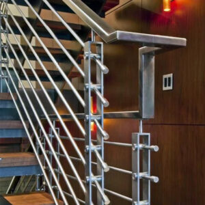
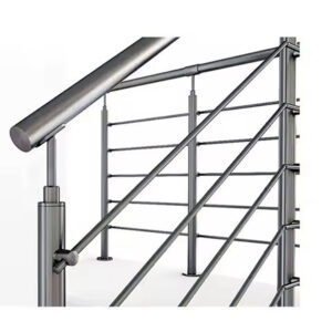
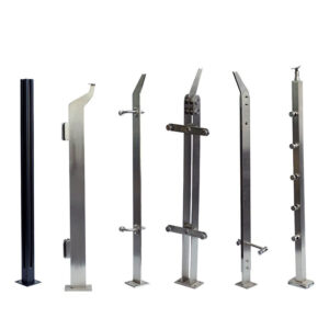
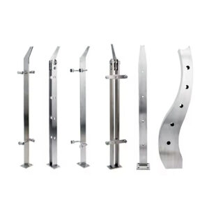
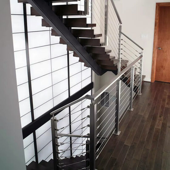
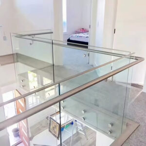
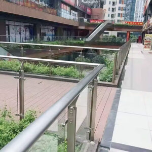
A railing run that moves from glass panels to cable infill, or back again, forces a decision long before shop drawings are finalized: which post carries which load, and where does one system’s hardware actually end. Designers often draw the transition as a clean visual joint, but the glass side and the cable side resolve force, fastening, and service access differently, and those differences do not announce themselves on an elevation drawing. The planning question is not whether the transition looks continuous but whether every interface underneath it has been identified and checked on its own terms.
Transition locations that must be identified before shop drawings
Before any shared-post or shared-rail decision can be made, every point where the infill type changes has to be located and listed. This includes corners, stair runs, gate openings, elevation changes, and the terminal ends of each tensioned cable run. Each of these is a distinct condition, not a variant of the same joint. A corner changes the direction a cable must travel and how a glass panel edge relates to the post face. A stair or elevation shift changes how datums align between glass and cable infill types, because rake angles affect panel bottom rails and cable spacing differently. A gate interrupts both systems and introduces hardware that neither pure glass nor pure cable runs require. The end of a tensioned run is a termination condition regardless of whether it occurs at a corner or along a straight run.
Treating these as one generic “transition” category during early planning creates a drawing that looks resolved but has not actually identified where the hardware changes. Where a project has several transition types in the same run, each one needs its own entry in the location list, because the fastening and access questions that follow are answered differently at a corner than at a stair nosing or a gate jamb. A location list that groups these together risks carrying an unresolved condition into shop drawings, where it becomes harder to correct once post layouts and panel orders are committed.
The practical value of a complete location list is that it defines the full set of interfaces that must be checked before any assumption about shared supports is accepted. Skipping a location, such as a minor elevation change partway down a run, does not remove the transition; it only postpones the point at which the project discovers that the glass support and cable terminal hardware were never coordinated at that point. Locating every change, including the less visible ones, is the input the next planning step depends on.
Shared-post assumptions versus separate glass and cable support zones
| Interface to check | Decision question | Boundary for the shared-support decision |
|---|---|---|
| Glass support | Is the proposed glass support resolved as its own interface? | Cable details do not establish the glass support arrangement. |
| Cable terminal forces | Are the terminal forces resolved independently from the glass support? | Glass support information does not establish the cable termination arrangement. |
| Fastening zones | Can the glass and cable interfaces use the proposed fastening zones without conflict? | A shared post or rail remains an assumption until both interfaces are checked together. |
| Installation and service access | Does each interface remain accessible for installation and later service? | Visual alignment alone does not establish workable access. |
Once transition locations are identified, the question becomes whether glass and cable can share a post or rail at each one, or whether they need separate support zones even when they sit close together. This is an assumption that has to be tested, not a default. A shared post looks efficient on a layout drawing, but glass support and cable terminal forces resolve through different mechanisms, and a post detailed for one does not automatically accommodate the other.
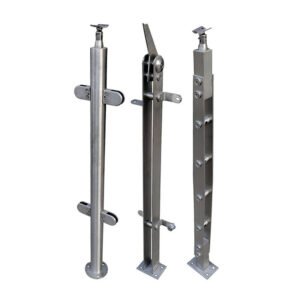
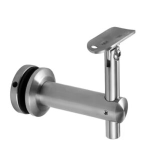
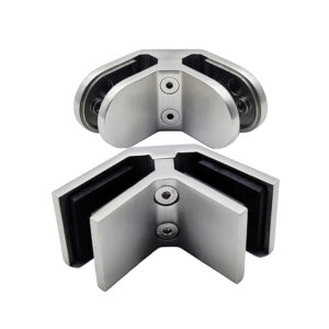
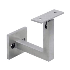
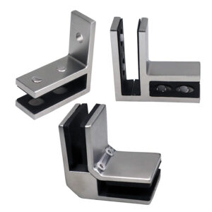
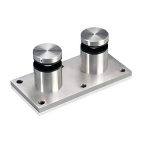
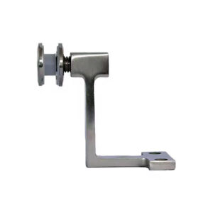
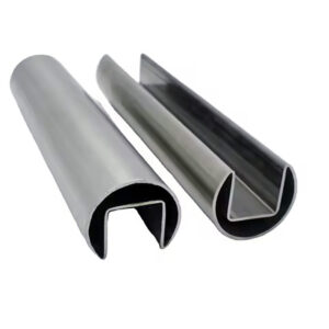
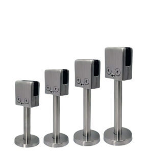
Glass support in a railing system typically resolves through a clamp, spigot, or adapter fastening into the post or structure, concentrating the panel’s load at discrete points along its edge. Cable infill resolves differently: the tension in a cable run applies a sustained pulling force at its terminal ends, and at a corner post that force changes direction, which can introduce a bending or torsional demand on the post that a glass-only post was never checked against. Where a post is expected to carry both a glass support interface and a cable terminal or run-through condition, the fastening zones for each may compete for the same face or elevation on the post, and the installation sequence for one can obstruct the other if they are not planned together.
Access is the fourth interface that a shared-post assumption can quietly compromise. Glass hardware may need clearance to install or later service a clamp or adapter; cable hardware needs tensioning access at its terminal. Where both are assigned to the same post, the physical space for one may not coexist with the access path for the other. Checking glass support, cable terminal forces, fastening zones, and access as four separate interfaces, rather than treating a shared post as a single resolved condition, is how a project confirms whether sharing is workable at a given transition or whether separate support zones are the safer planning path. Where glass and cable loads are both substantial at a single point, separate zones remove the competition for post geometry even if they require an additional post in the run.
Glass panel, clamp, adapter, rail, and replacement-clearance interfaces
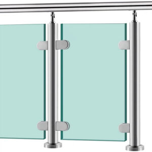
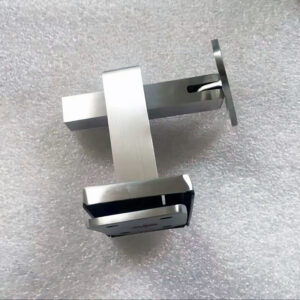
At a glass-to-cable transition, the glass side of the joint is not a single part but a chain of interfaces: the panel edge, the clamp or spigot fastening it, any post-to-glass adapter resolving an offset or alignment difference, and the rail or cap that sits above or alongside it. Each of these interfaces has its own clearance requirement, and at a transition point that clearance can be reduced by whatever cable hardware sits on the adjacent side of the same post.
A post-to-glass adapter exists specifically to resolve a mismatch between a post’s mounting face and a panel’s required position or angle, which is common at transition points because the post may be sized or located to also serve the cable side. Where an adapter is introduced to solve that alignment problem, it adds a layer to the replacement path: a damaged panel cannot be removed without first addressing whatever sits between the clamp and the post. If cable terminal hardware or a corner fitting has been mounted close to that adapter, the sequence for removing the glass panel may now require disturbing the cable hardware as well, even though the two systems are otherwise independent.
This is the condition that replacement planning has to anticipate rather than discover later. A glass panel, its clamp, an adapter, and the adjoining rail form one connected access path; if any part of that path becomes blocked by a finish, a cap, or an adjacent cable fitting installed without clearance in mind, replacing the panel means disturbing hardware that was not supposed to be part of the glass system’s service scope. The same logic applies in reverse: cable terminal hardware installed tightly against a glass adapter may become inaccessible once trim or finish work closes the gap between the two systems. The planning task is to confirm, for each transition, that the full chain of glass interfaces can be reached and serviced without requiring removal of cable-side hardware, and that the reverse is also true.
Cable terminal forces, corner routing, tensioning access, and end conditions
| Cable-run check | What the drawing must make clear | Decision supported |
|---|---|---|
| Terminal forces | How cable terminal forces are addressed at the transition | Whether the cable termination can be assessed separately from glass support |
| Corner routing | How the cable route changes at each corner | Whether the corner condition is fully identified before approval |
| Tensioning access | Where tensioning access is retained | Whether adjacent finishes would obstruct cable adjustment |
| End conditions | Where each tensioned run ends | Whether every termination point has been located for review |
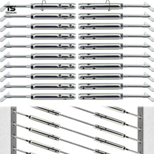
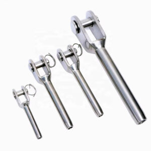
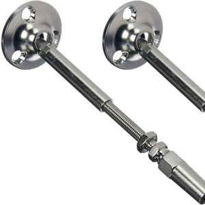
The cable side of a transition carries its own set of conditions that a drawing has to resolve independently of the glass side. Cable terminal forces behave differently from glass loads because a tensioned cable applies a continuous pulling force concentrated at its end fitting, and that force has to be resolved into the post or structure at the termination point regardless of what glass hardware shares the same post. Where a termination occurs near a glass-to-cable transition, the drawing needs to make clear how that force path is addressed separately from whatever is resolving the glass panel’s load at the same location.
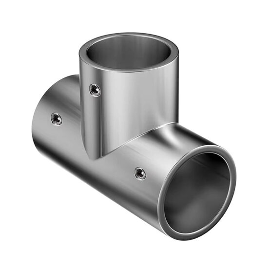
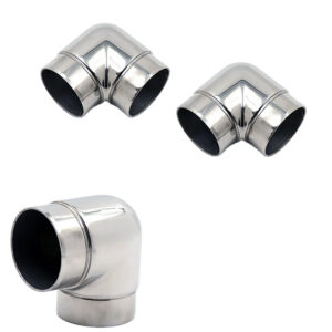
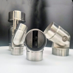
Corner routing changes the direction a cable travels and typically requires hardware suited to that direction change, which is a different condition from a straight run passing through intermediate posts. At a transition that also happens to fall on a corner, the routing hardware and the glass support arrangement are both competing for position on the same post, and the drawing has to show how each is accommodated without one obstructing the other’s fastening or access.
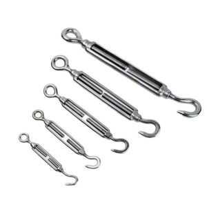
Tensioning access is a condition that is easy to resolve on paper and lose during installation. A cable run needs a point where tension can be applied and later adjusted, and that point has to remain reachable after adjacent finishes, caps, or glass hardware are installed. Where a transition places tensioning hardware close to a glass panel or adapter, finishing work on the glass side can close off the clearance the cable side needs for adjustment, even though the two systems were detailed by different trades.
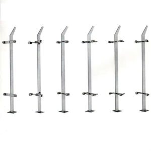
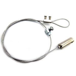
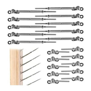
End conditions, the point where each tensioned run terminates, have to be located explicitly rather than assumed to coincide with a convenient post. A run may end at a corner post, at a transition to glass, or at an intermediate point, and each of these is a distinct termination condition with its own force path and access requirement. A drawing that shows a cable run entering a transition without identifying exactly where that run ends has not yet resolved the termination, and reviewing corner post cable hardware and the adapters used on the glass side together, before approval, is how the project confirms whether both the termination and the adjoining glass interface have been coordinated rather than assumed.
Alignment of rails, infill datums, post faces, gaps, finishes, and drainage
Once the structural and access interfaces at a transition are resolved, the visual alignment of the joint still has to be checked on its own terms, because a clean-looking junction can conceal a conflict that the structural review already missed or that only becomes visible once dimensions are drawn together. Top rails and handrails on the glass and cable sides may be supplied by different hardware and need to meet at a common height and profile; a mismatch here is not merely cosmetic, because a rail that steps or shifts at the transition can also signal that the post faces supporting each side are not coplanar.
Infill datums, the reference lines that set where glass panels and cable rows begin and end vertically, need to align across the transition even though glass and cable achieve their spacing differently. A glass panel’s bottom and top edges are fixed by the panel dimension and the clamp or spigot position, while cable rows are set by the spacing between individual cables. Where these datums are not planned against a common reference, the two infill types can appear to drift relative to each other across the joint, which is a sign that the layout was resolved separately for each side rather than together.
Gaps between the two systems have functional significance beyond appearance. A gap sized without reference to both systems’ governing clearances can be too tight for the access path a glass panel or cable terminal needs, or too wide relative to whatever opening limit applies to the infill type. Finishes matter at the same joint because a cap, trim piece, or coating applied across the transition after both sides are installed can close off a clearance that was open during the structural check.
Drainage is the condition most likely to be overlooked at a transition because neither the glass detailing nor the cable detailing treats it as their responsibility alone. A post or base condition that manages water for a glass panel assembly may not do the same for an adjoining cable termination, and where the transition sits at a point where water collects, the alignment review has to confirm that drainage continues through the joint rather than stopping at whichever system’s detail happened to include it.
Drawing approval after structural, installation, and maintenance responsibilities align
A transition drawing is ready for approval only after the structural, installation, and maintenance responsibilities for that specific joint have been assigned and agreed among the project parties, not merely after the geometry has been checked. Structural responsibility covers which party has confirmed that the glass support and the cable terminal forces at the transition have been resolved into the post or structure; this is a distinct sign-off from the visual or dimensional coordination described earlier, because a drawing can be dimensionally consistent while leaving the force path unconfirmed.
Installation responsibility addresses sequencing: which trade installs which hardware first at a shared post, and whether that sequence respects the access and clearance conditions identified for both the glass and cable interfaces. Where a transition requires glass hardware and cable termination hardware to occupy close positions on the same post, an installation sequence agreed in advance prevents one trade’s work from blocking the other’s fastening zone.
Maintenance responsibility is the condition most often left unresolved because it has no immediate bearing on whether the drawing looks complete. It covers who can access the transition later for panel, cable, terminal, gasket, or fastener replacement, and whether that access remains available once adjacent finishes are in place. A drawing that passes structural and installation review can still leave a maintenance gap if no party has confirmed that the replacement path identified during planning remains valid after all trades have finished their work.
Where project evidence establishes which party owns each of these three responsibilities at a given transition, approval can proceed on that basis; where it does not, the open item is not a dimensional or structural question but an assignment question, and the project team needs to confirm who signs off on each responsibility before the drawing is treated as final. The post-mounting method comparison and the corner-post and termination hardware design questions developed earlier in project planning are the kind of coordination record that supports this sign-off, because they document how the structural and installation questions were resolved before the maintenance question is asked.
Frequently Asked Questions
Q: Can one transition detail be reused at corners, stairs, gates, and elevation changes?
A: Only when the glass support, cable routing and termination, fastening zones, alignment, and service access are genuinely the same. Identify each transition location first, then group only the conditions that can be reviewed with one complete detail.
Q: What project information should be prepared before deciding whether glass and cable can share a post or rail?
A: Prepare the proposed glass support, cable terminal-force approach, fastening zones, and installation and service access for the junction. A shared support should remain an open decision until those interfaces have been checked together.
Q: How can the design preserve future replacement access at a mixed railing transition?
A: Trace a removal path for the glass panels, cables, terminals, gaskets, and fasteners before adjacent finishes are fixed. The drawings should show where adjustment or removal occurs and which nearby work must remain accessible.
Q: Do the cited glazing and wire-rope standards establish the complete mixed railing design?
A: No. ASTM E2358 addresses glazing in permanent railing systems, while ISO 2408 addresses steel wire ropes within its stated scope; neither by itself resolves cable terminals, post spacing, project code requirements, or the combined transition. Confirm the project-specific requirements and assign the remaining design decisions to the appropriate project parties.
Q: When is a glass-to-cable transition ready for shop-drawing approval?
A: It is ready when every transition is located and the support, terminal, fastening, routing, alignment, drainage, installation, and maintenance interfaces are resolved. Any project-dependent item that remains undecided should be identified for resolution before approval.